FST Cardioid
With the rising popularity of cardioid speakers I thought it about time I give one a go. Given how much I love the sound of constant directivity waveguides and coaxials it made sense to see what things would be like if you extended that range down below where the typical tweeter stops.
A passive cardioid cabinet design places greater demands on the driver it's intended to work with but as I am no longer listening at particularly high SPLs this seemed like a decent trade off.
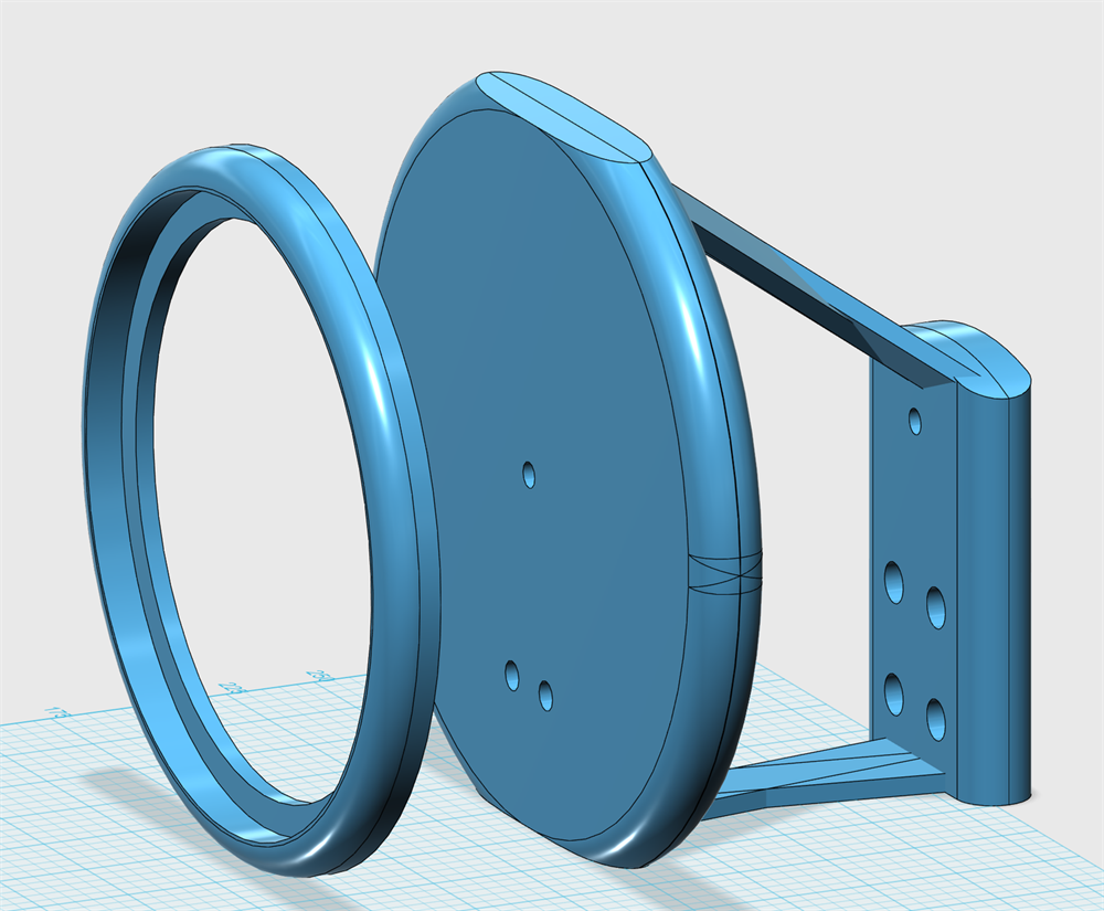
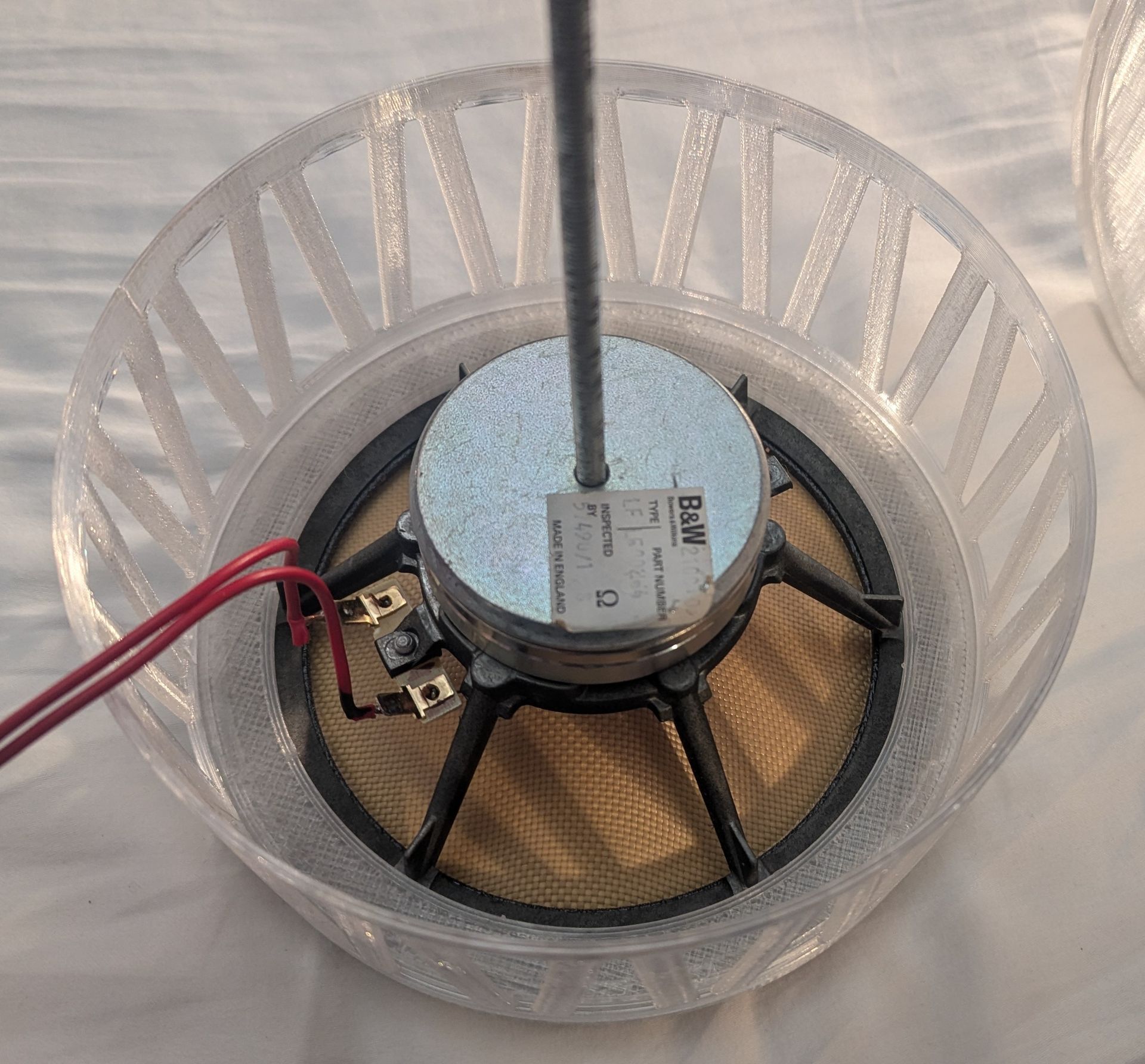
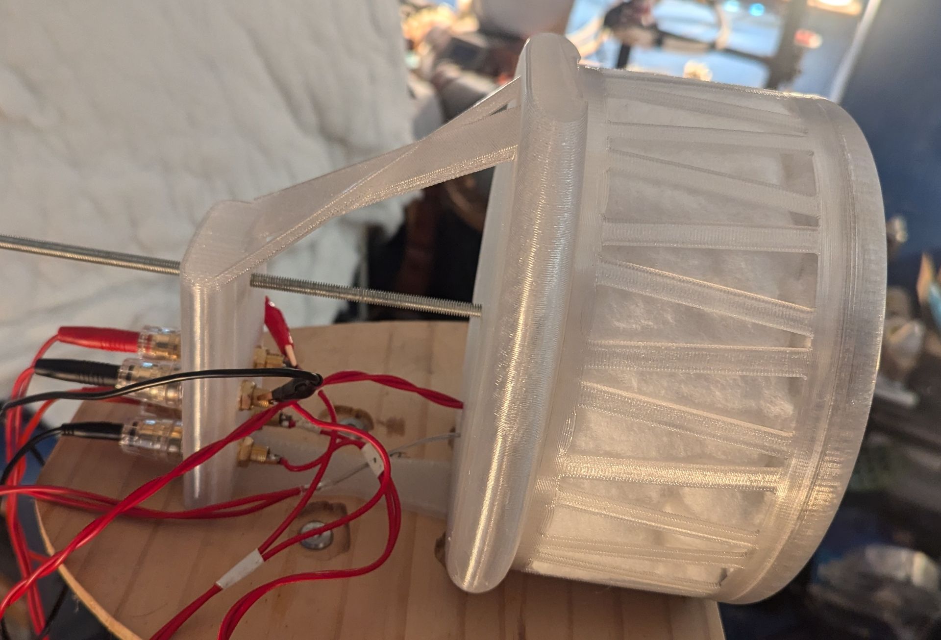
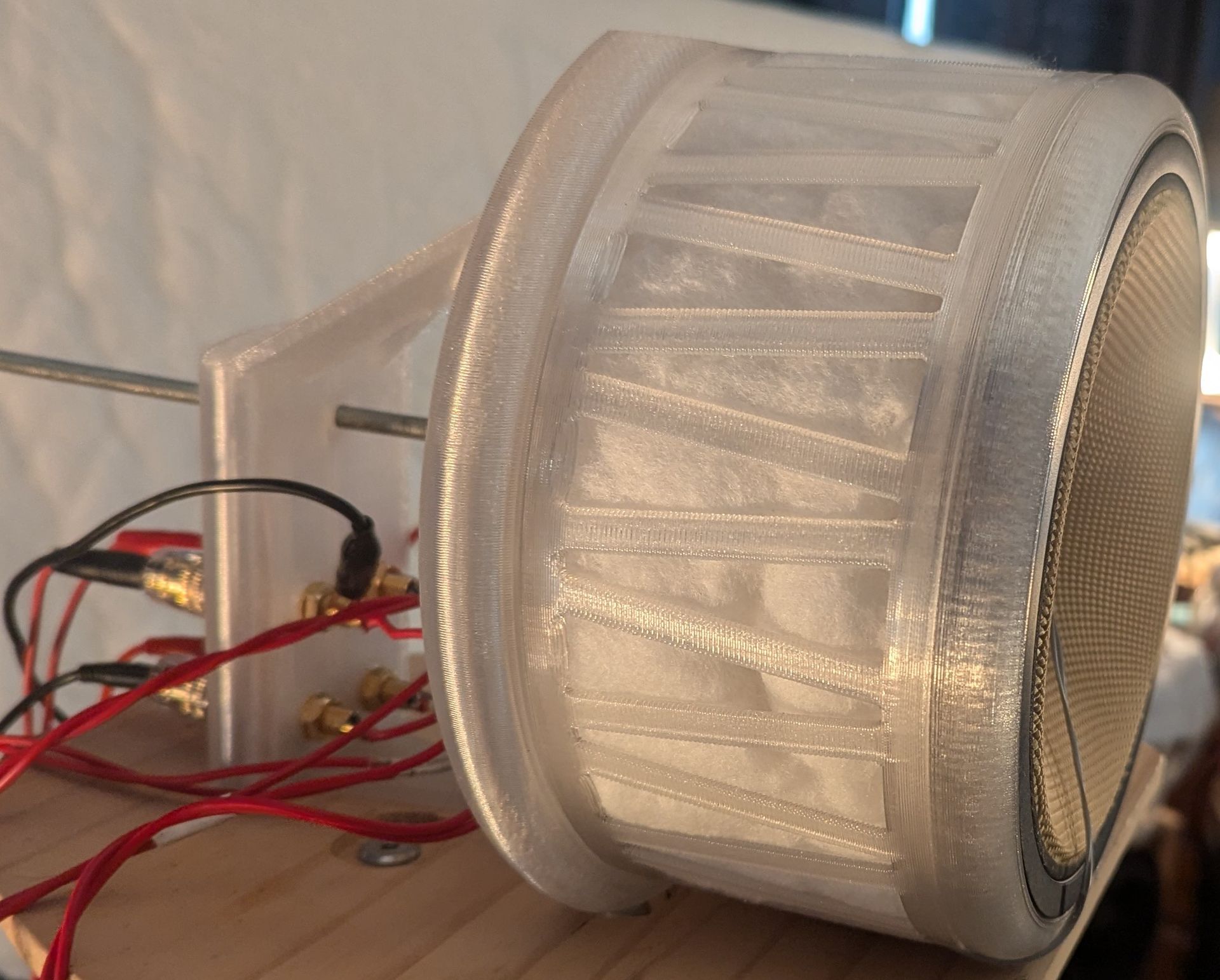
Below are a set of pictures showing the development of a cardioid concept for the FST coax. The cabinet was 3D printed.
A passive cardioid cabinet design places greater demands on the driver it's intended to work with but as I am no longer listening at particularly high SPLs this seemed like a decent trade off.
Below are a set of pictures showing the development of a cardioid concept for the FST coax. The cabinet was 3D printed.
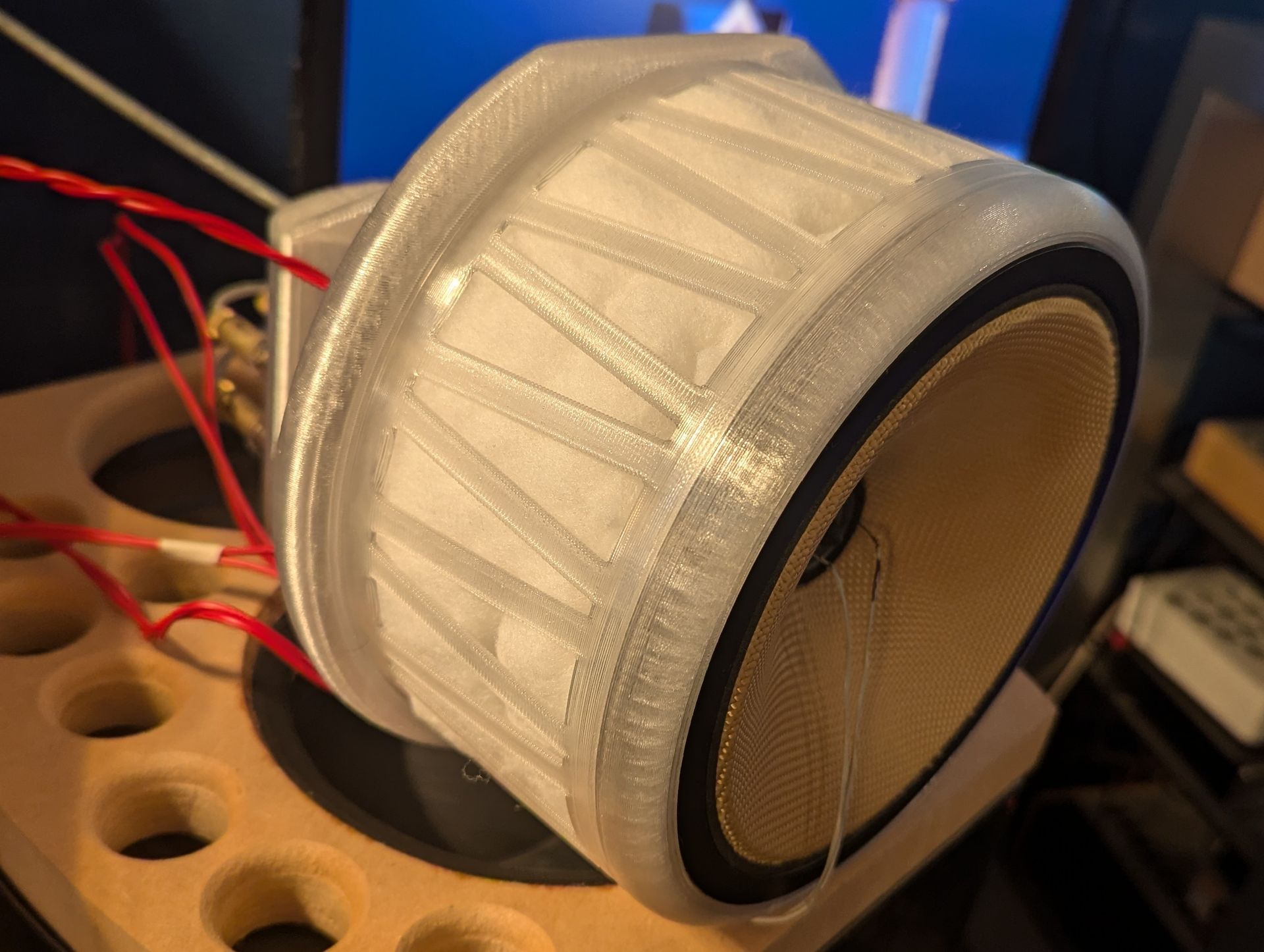
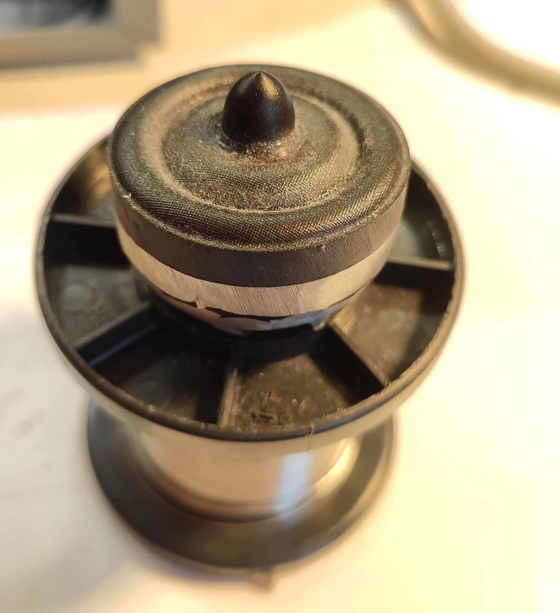
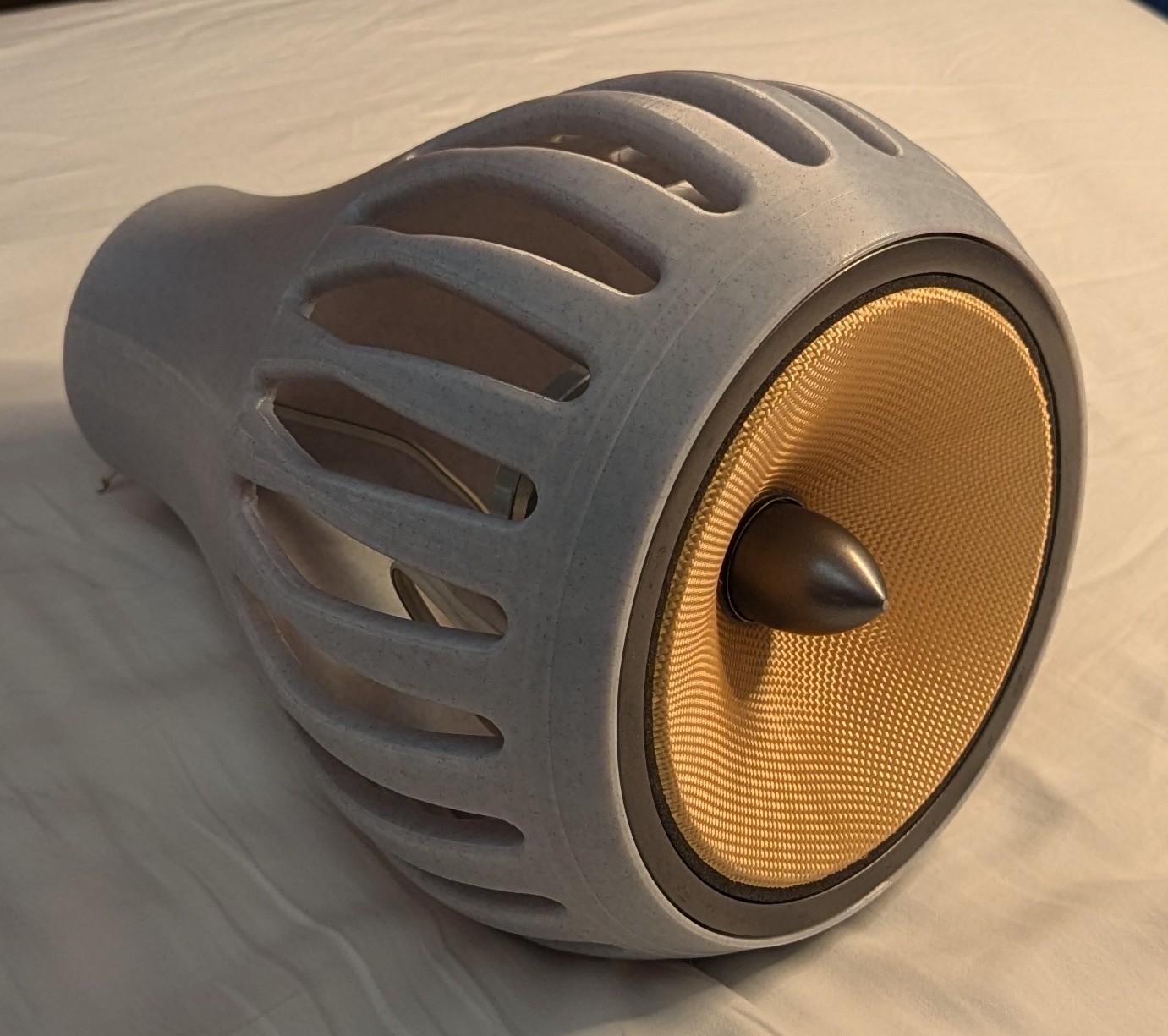
A while ago I had changed the FSTs coax tweeter to the OT19. I'd had these sitting on a shelf for a while but thought I'd end up destroying them trying to get them to fit. As a result they stayed sitting on the shelf but curiousity got the better of me so I took them to the sanding machine. Turns out you can just about get them trimmed down enough to fit.
OT19 curves mounted in the FST. Very nice!
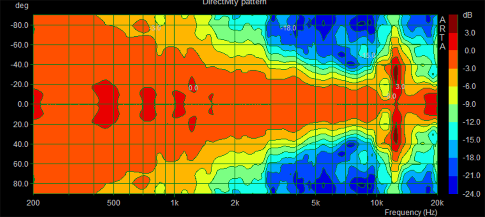
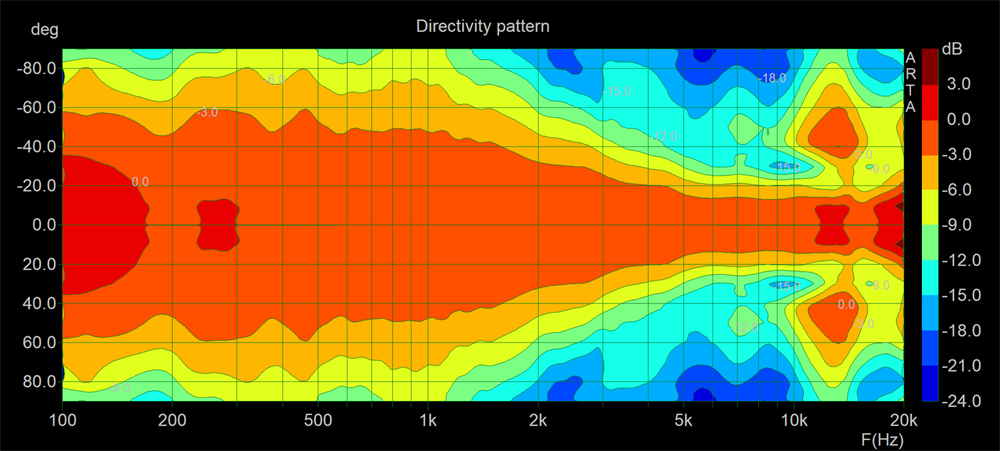
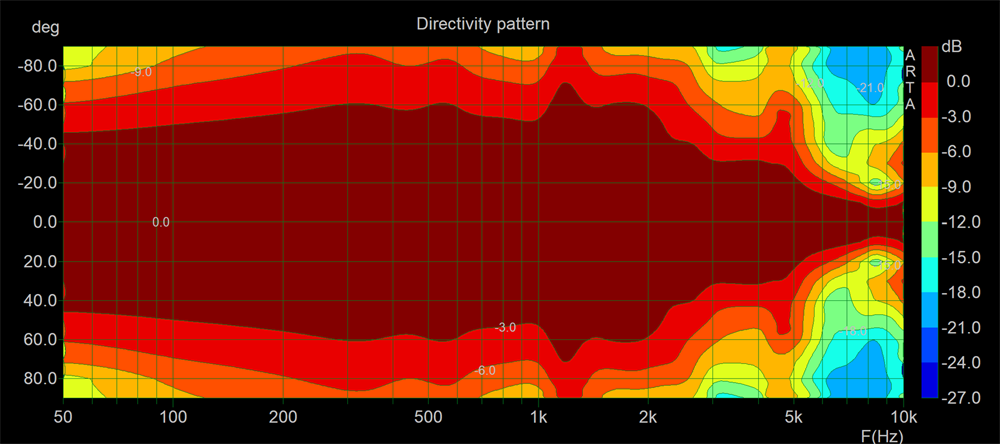
Here is a directivity plot showing the response of the FST in the spherical cabinet I made years ago.
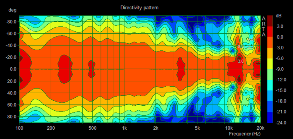
And here is the FST in the cardioid test cabinet. Not bad although a little narrower than a true cardioid. No bad thing in my opinion.
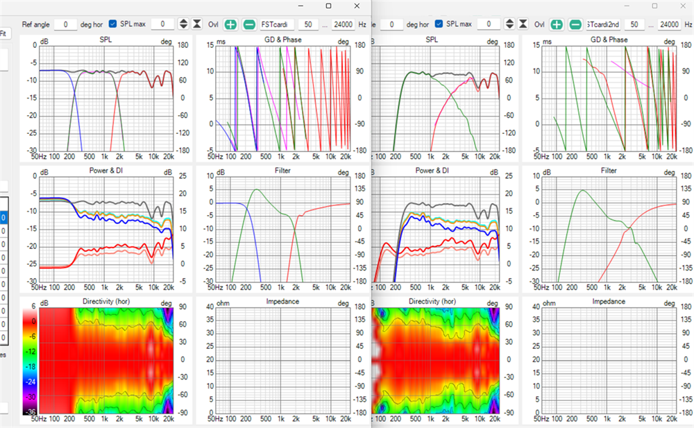
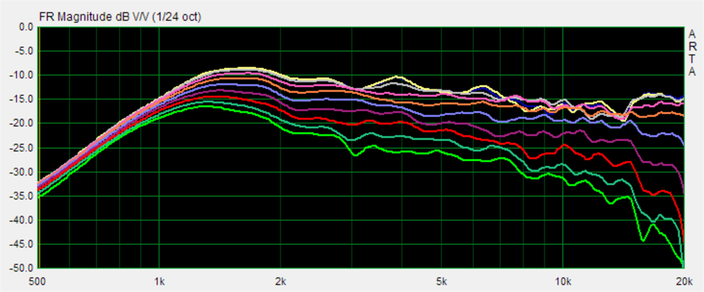
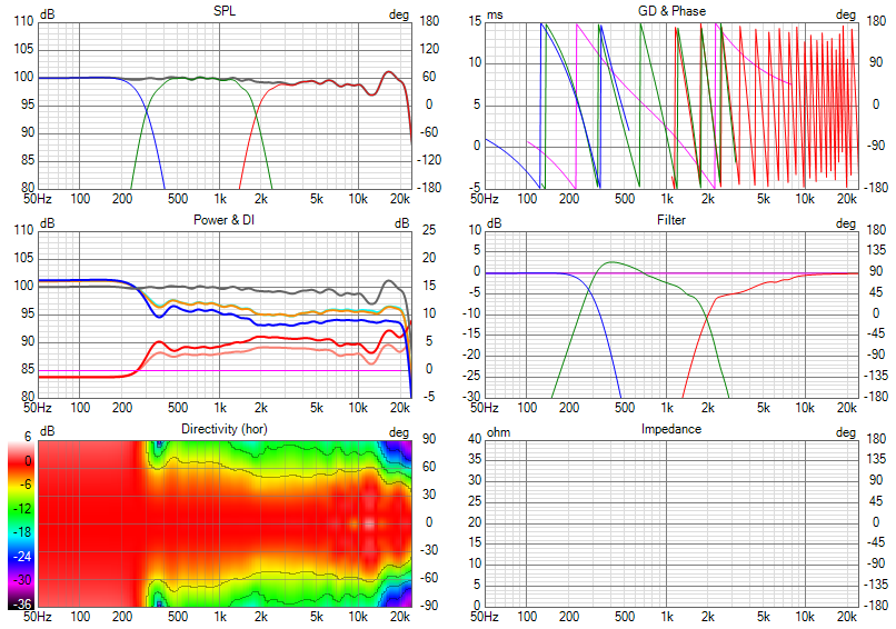
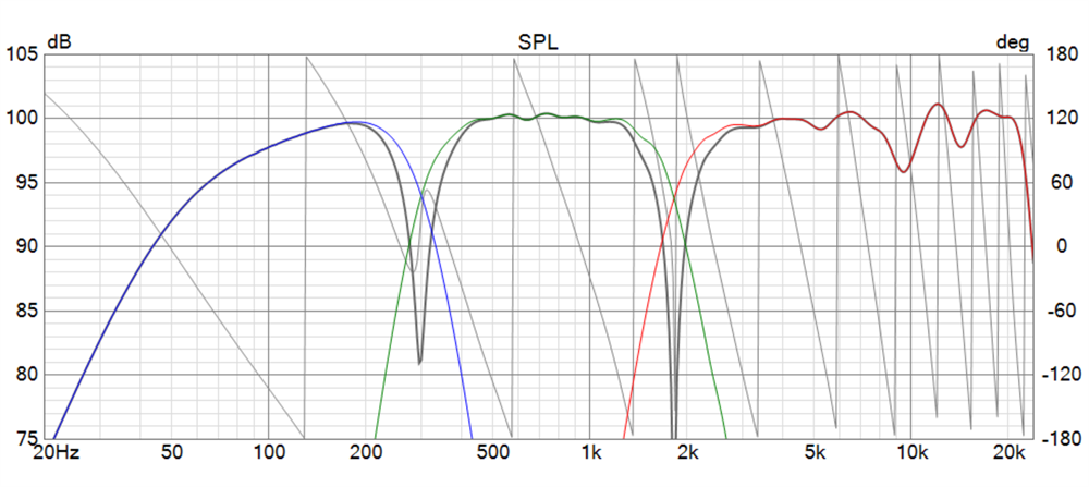
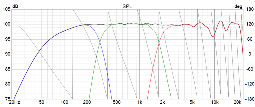
Above shows two crossovers. The first gets the best directivity and required an 8th order target slope on the OT19 at 1.8kHz. This is really rather low but thanks to the tweeter having a very extended low end for its size, and the waveguide loading, it managed it quite well. The other was a 4th order at 2.5kHz but as is evident it's not as uniform.
If you're trying to get it to go as low as possible then the FST absolutely needs a 6th, or greater, order high pass to function well in a cardioid. In a closed cabinet it needs a 4th order, so in combination with the low frequency cardioid EQ needed, you need to increase the filter order to counter the EQ below the xover frequency.
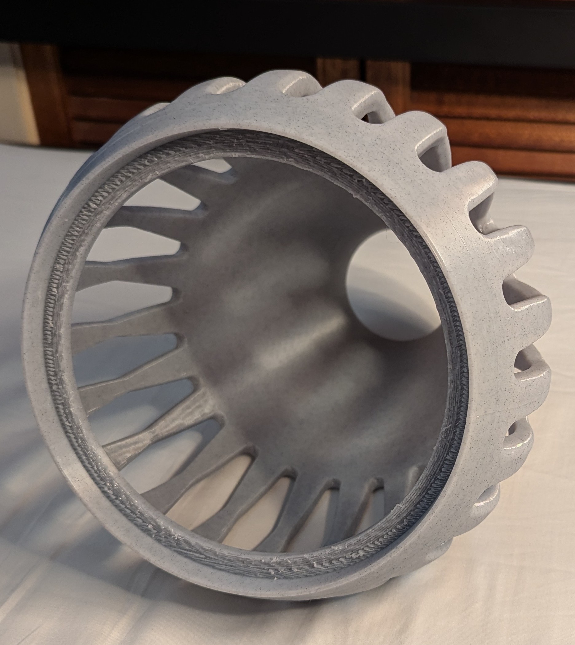
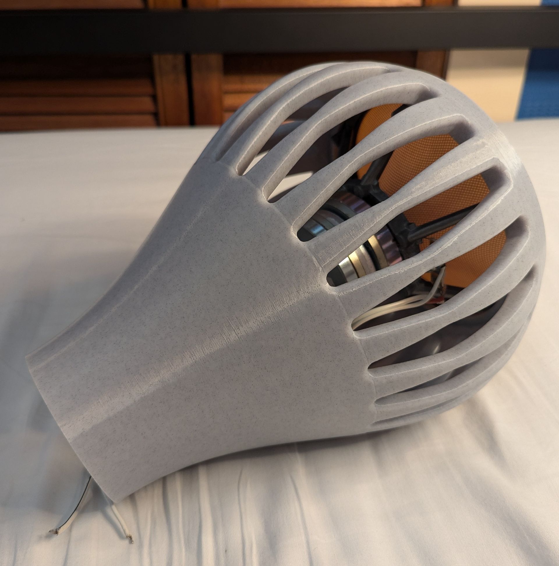
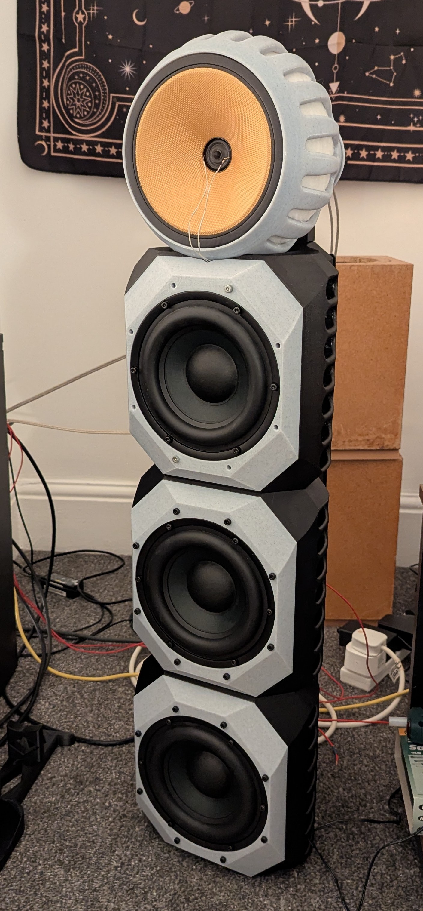
It sounded great and given the success I had to go with something a little more permanent than the concept shell.
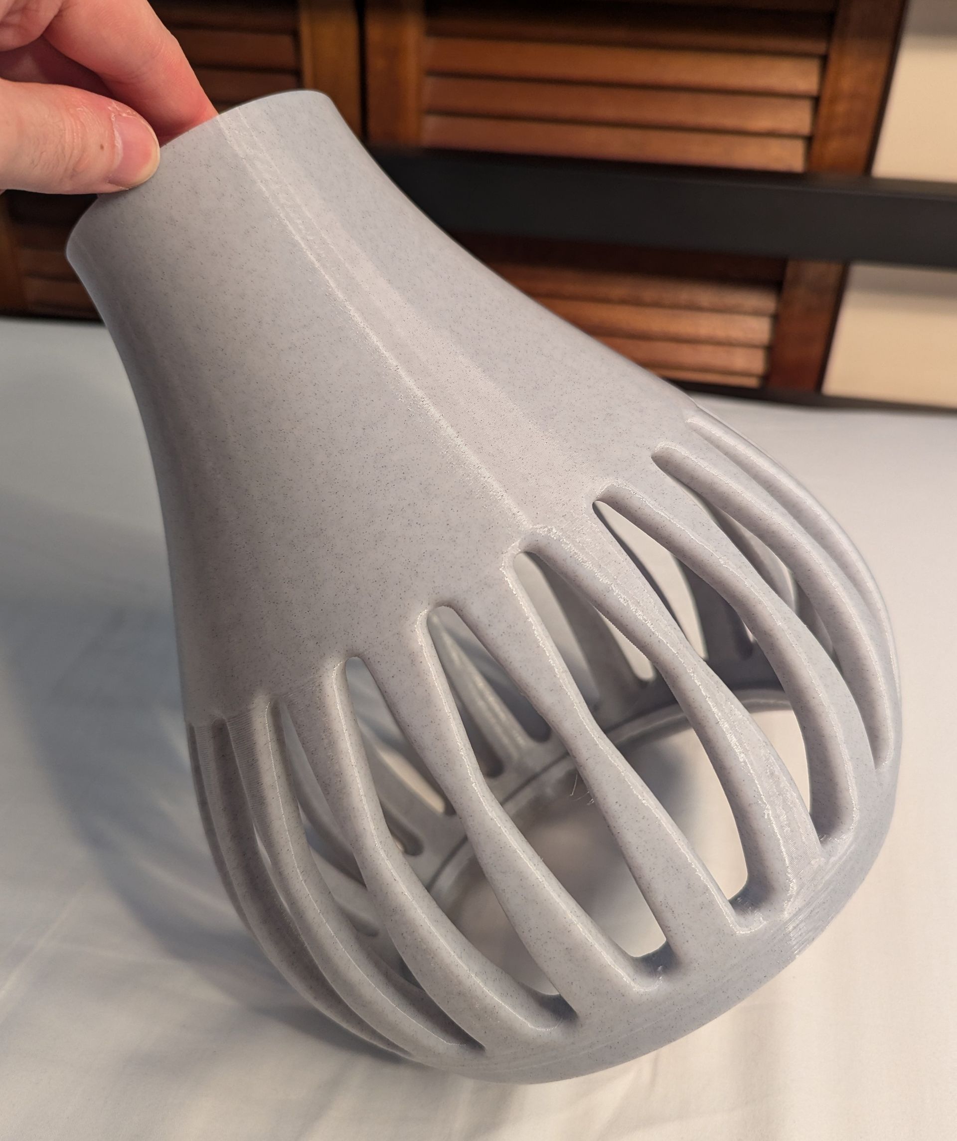
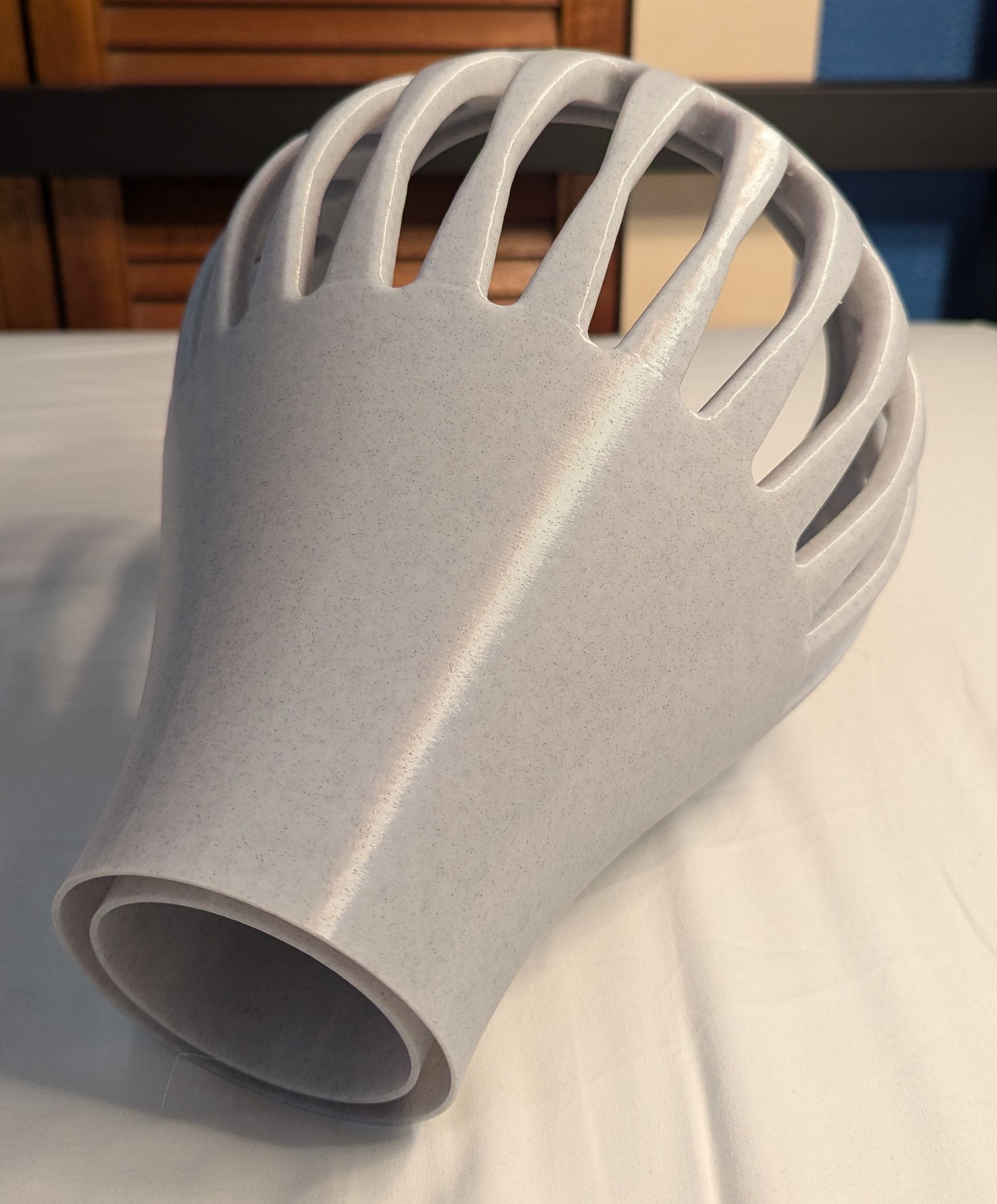
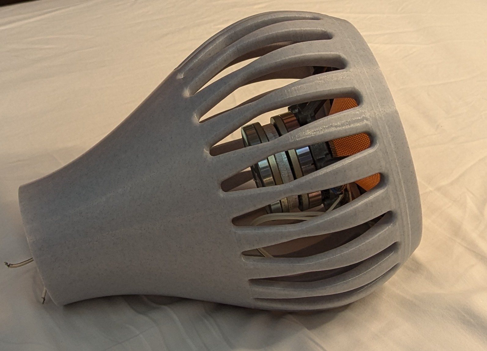
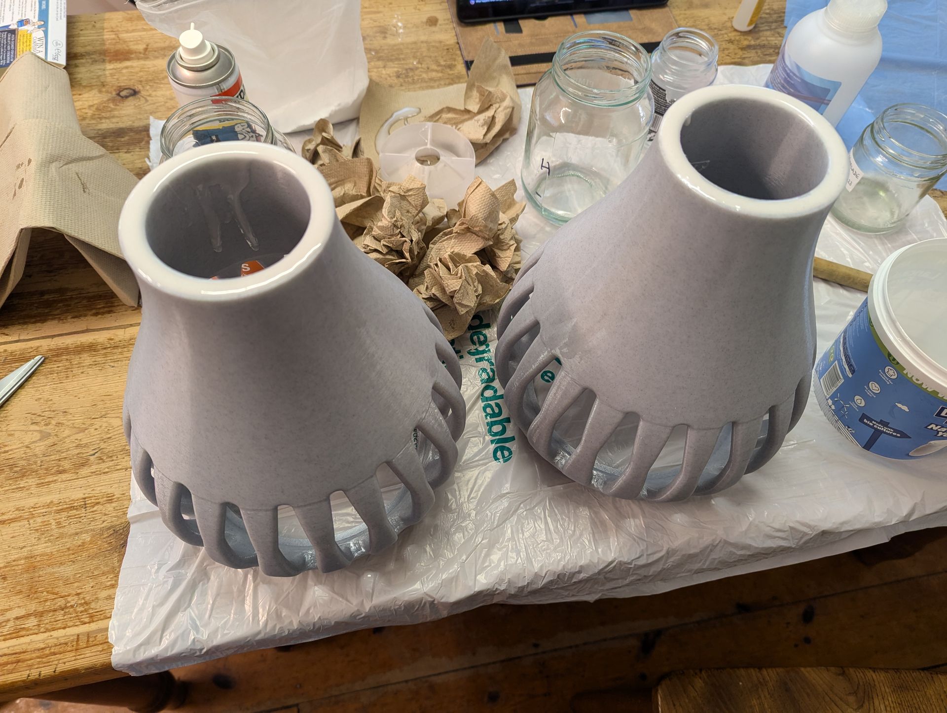
Below are a series of pictures showing the next iteration. These were 3D printed too in a stone effect filament. The cabinets were printed as a hollow shell and then filled with expoxy loaded with marble dust. The dust is cheap and adds bulk and weight to the cabinet. This is much the same process by which I made the original B&W nautilus clone but with a 3D printer things are much easier.
If you're trying to get it to go as low as possible then the FST absolutely needs a 6th, or greater, order high pass to function well in a cardioid. In a closed cabinet it needs a 4th order, so in combination with the low frequency cardioid EQ needed, you need to increase the filter order to counter the EQ below the xover frequency.
It sounded great and given the success I had to go with something a little more permanent than the concept shell.
Below are a series of pictures showing the next iteration. These were 3D printed too in a stone effect filament. The cabinets were printed as a hollow shell and then filled with expoxy loaded with marble dust. The dust is cheap and adds bulk and weight to the cabinet. This is much the same process by which I made the original B&W nautilus clone but with a 3D printer things are much easier.
Below are plots showing the frequency response of the FST in the new cabinet. First a standard off-axis plot and then a normalised contour.
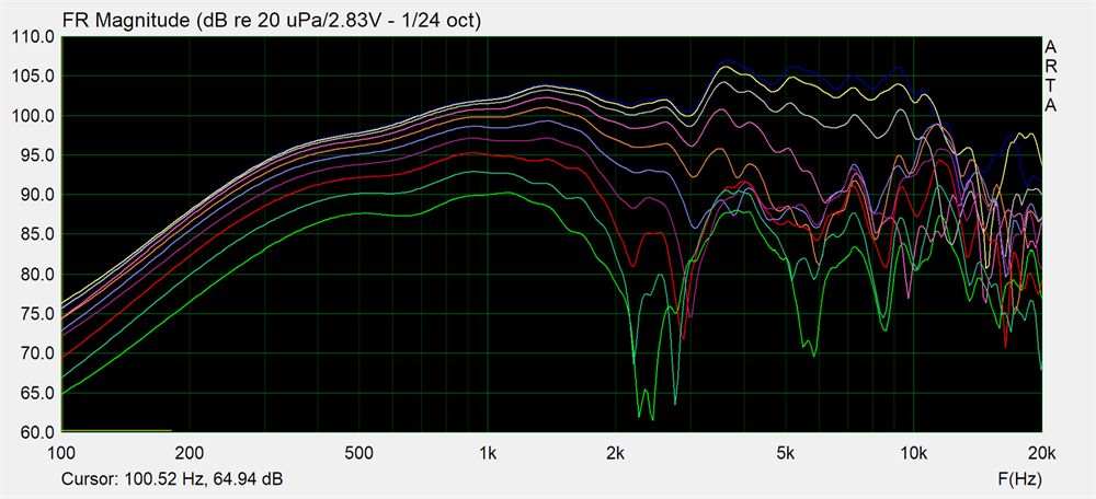
This is why we get worked up about diffraction control. Look at smooth that is from 500Hz to 10kHz. The few wiggles below 500Hz are because of the room creeping in with the long gate. This cannot be helped given the in-room measurements.
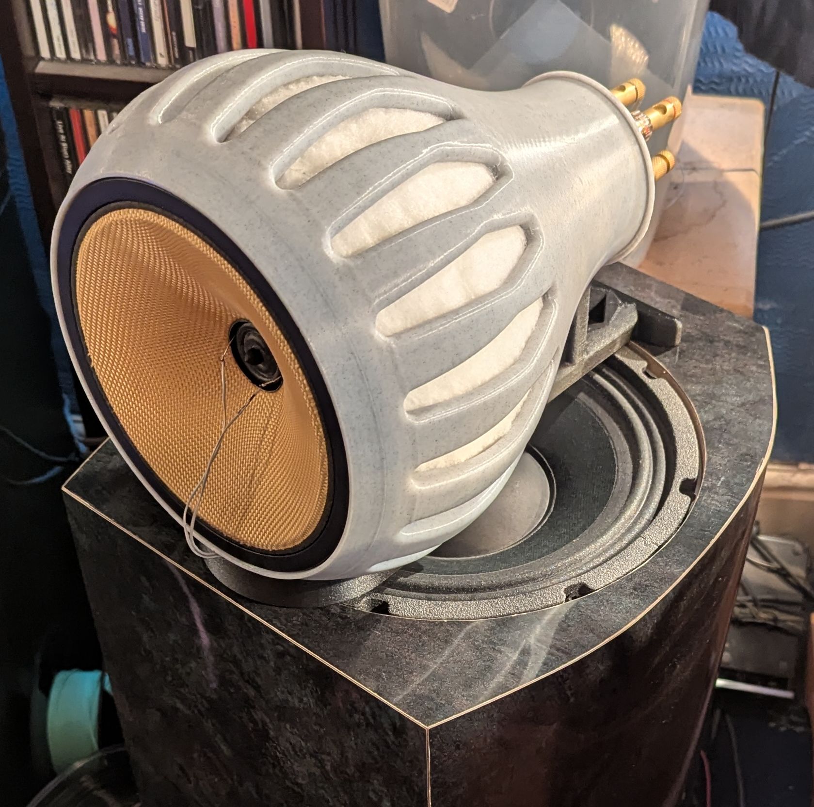
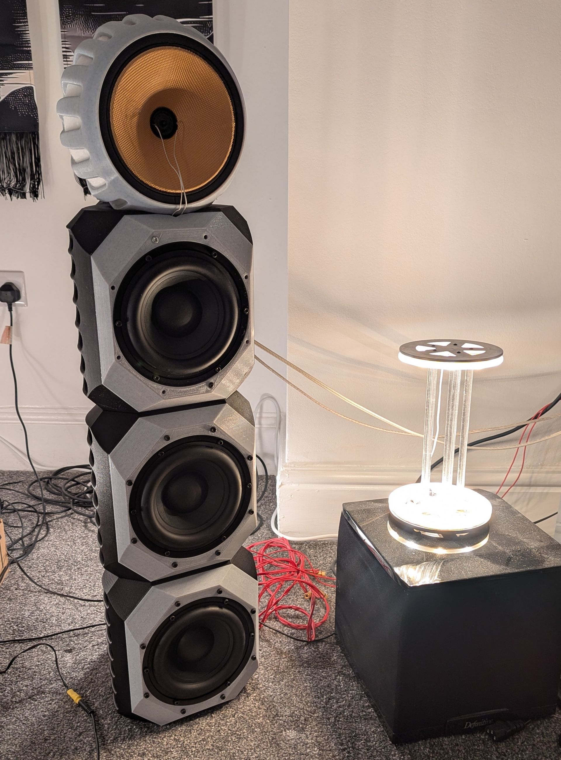
And the final result.
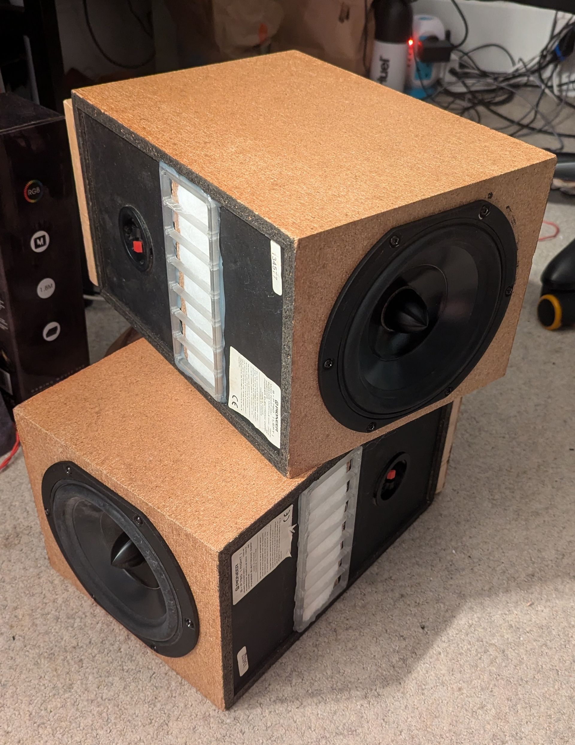
Up until now I had been doing all of my listening complimenting the cardioid with the bass from the FSTNT1 well I wanted to try taking the cardioid down even further. One of the main ideas behind the cardioid concept, and then potentially remaking the speakers if it was a success, was to size things down. Some of you will probably laugh at the idea of trying a cardioid bass concept with a 6.5" bass driver but I figured why not give it a go.
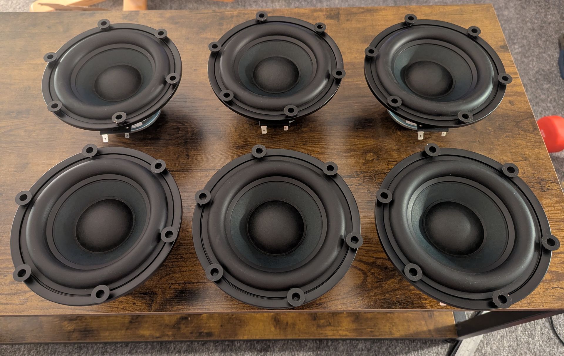
So I modified some junk cabinets and got out a pair of good old Peerless HDS 850467s.
Up until now I had been doing all of my listening complimenting the cardioid with the bass from the FSTNT1 well I wanted to try taking the cardioid down even further. One of the main ideas behind the cardioid concept, and then potentially remaking the speakers if it was a success, was to size things down. Some of you will probably laugh at the idea of trying a cardioid bass concept with a 6.5" bass driver but I figured why not give it a go.
So I modified some junk cabinets and got out a pair of good old Peerless HDS 850467s.
The 850467s were part of Peerless' original HDS line and were the first serious pair of woofers I ever bought. I was 15 at the time, didn't know much about drivers, but knew I wanted the drivers with the shiny phase plugs. Little did I know how good they were at the time.
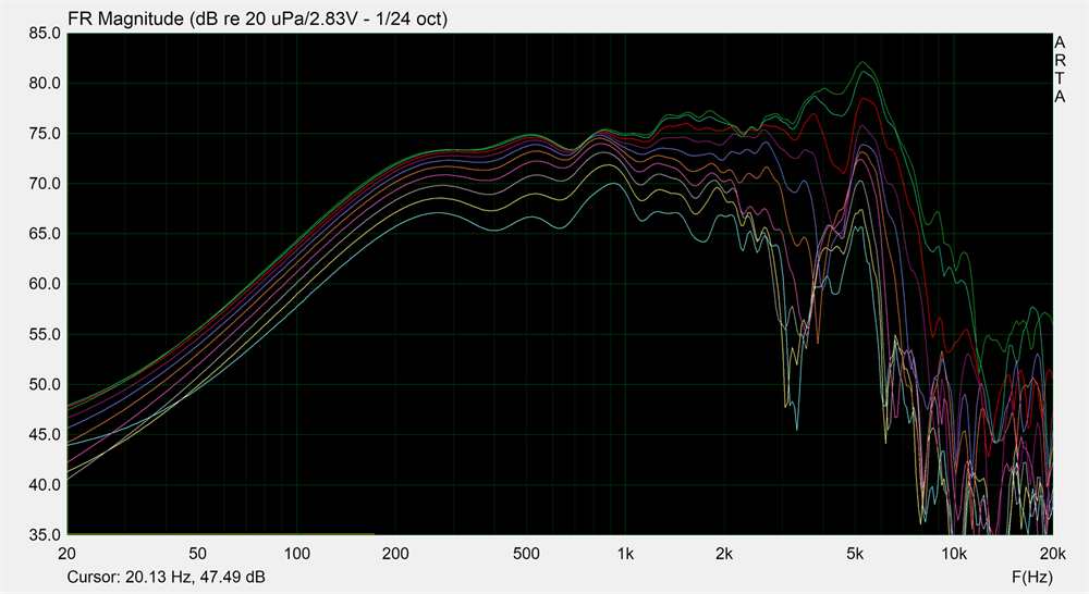
To refresh my memory I first performed a distortion sweep at 2.83VRMS. This was something I'd never done for these and I was pleasantly surprised.
To refresh my memory I first performed a distortion sweep at 2.83VRMS. This was something I'd never done for these and I was pleasantly surprised.
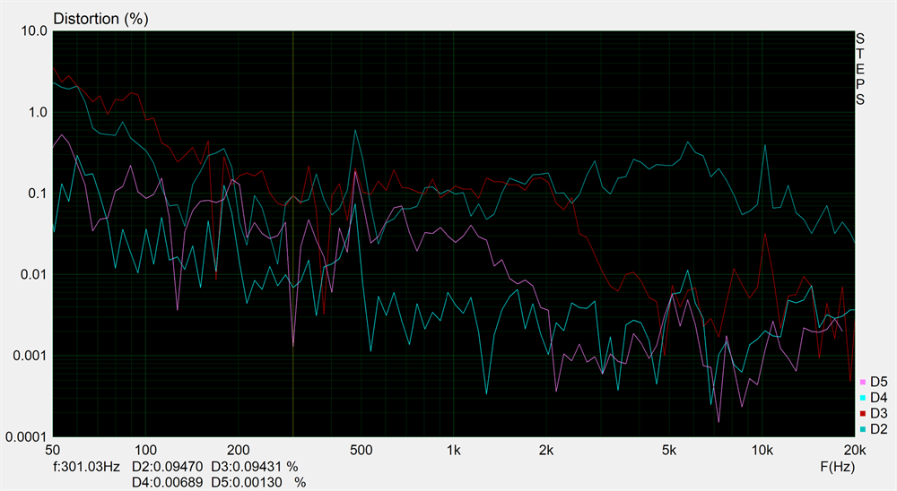
There I was expecting them to have rising third order, like much of the other HDS drivers, but it's perfectly flat! Not to mention very low. No wonder I thought they sounded clean.
More decent cardioid performance but with an obvious need for hefty amounts of bass EQ. Placed under the cardioid FST coax they sounded very good. I EQd them to provide decent bass extension down to 50Hz and then rolled them off quickly below.
Having been very satisfied with the experiment into cardioid bass I decided it was worthwhile going the whole hog and finishing up a speaker using a stack of 6.5" bass drivers. There aren't a whole lot of high excursion, low inductance, drivers on the market at a reasonable price but I decieded upon using the BWX-6502 from Bold North Audio. These had been measured by Vance Dickason and had Klippel verified excursion out to 9mm. Not to mention low enough lower midrange distortion and an attractive price.
As luck would have it I found a close-out sale that a German distributor was having and managed to snap up 6 of them for 100 euros a piece. Quite the bargain and you can see my measurements of them here.
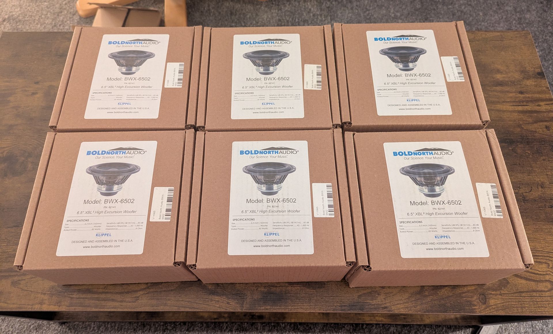
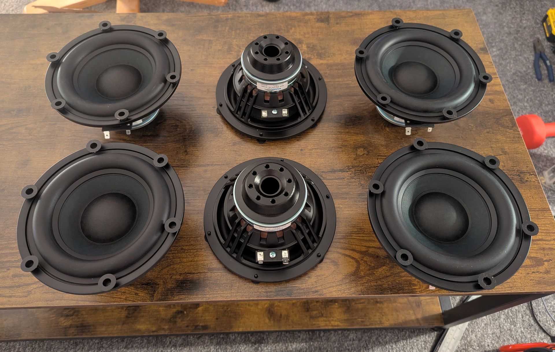
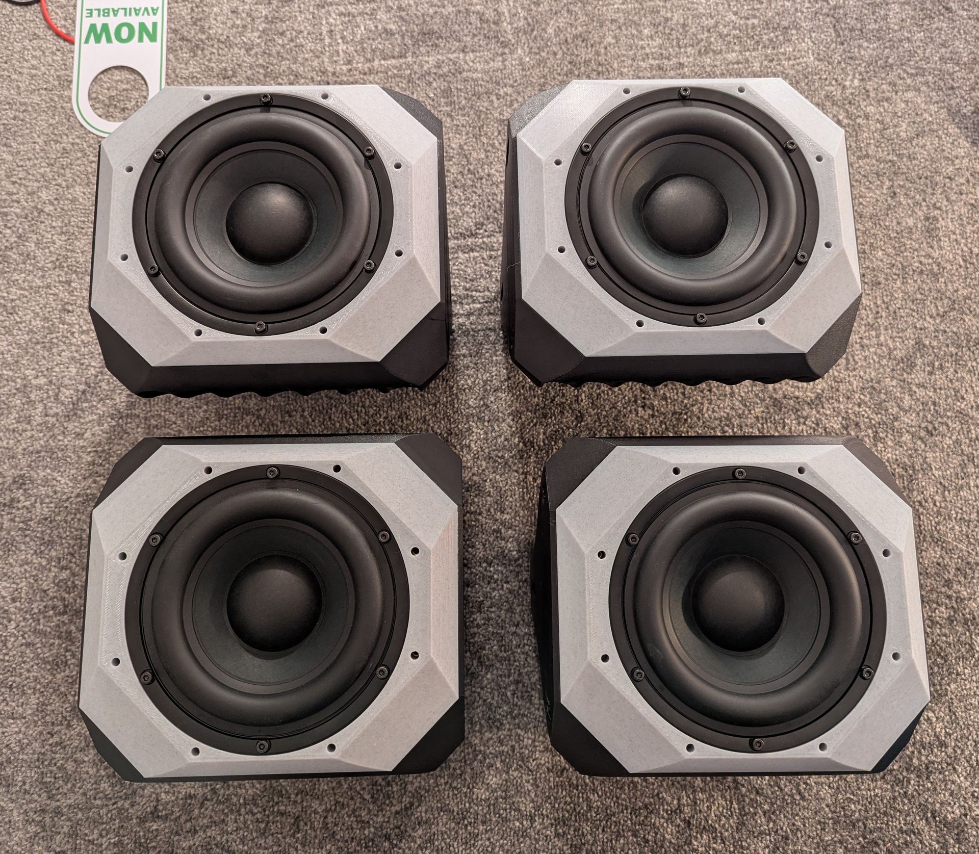
They definitely look the part although I do wish they had an aluminium cone although for this application it would make no difference to their performance. Now I needed some cabinets but first of all...
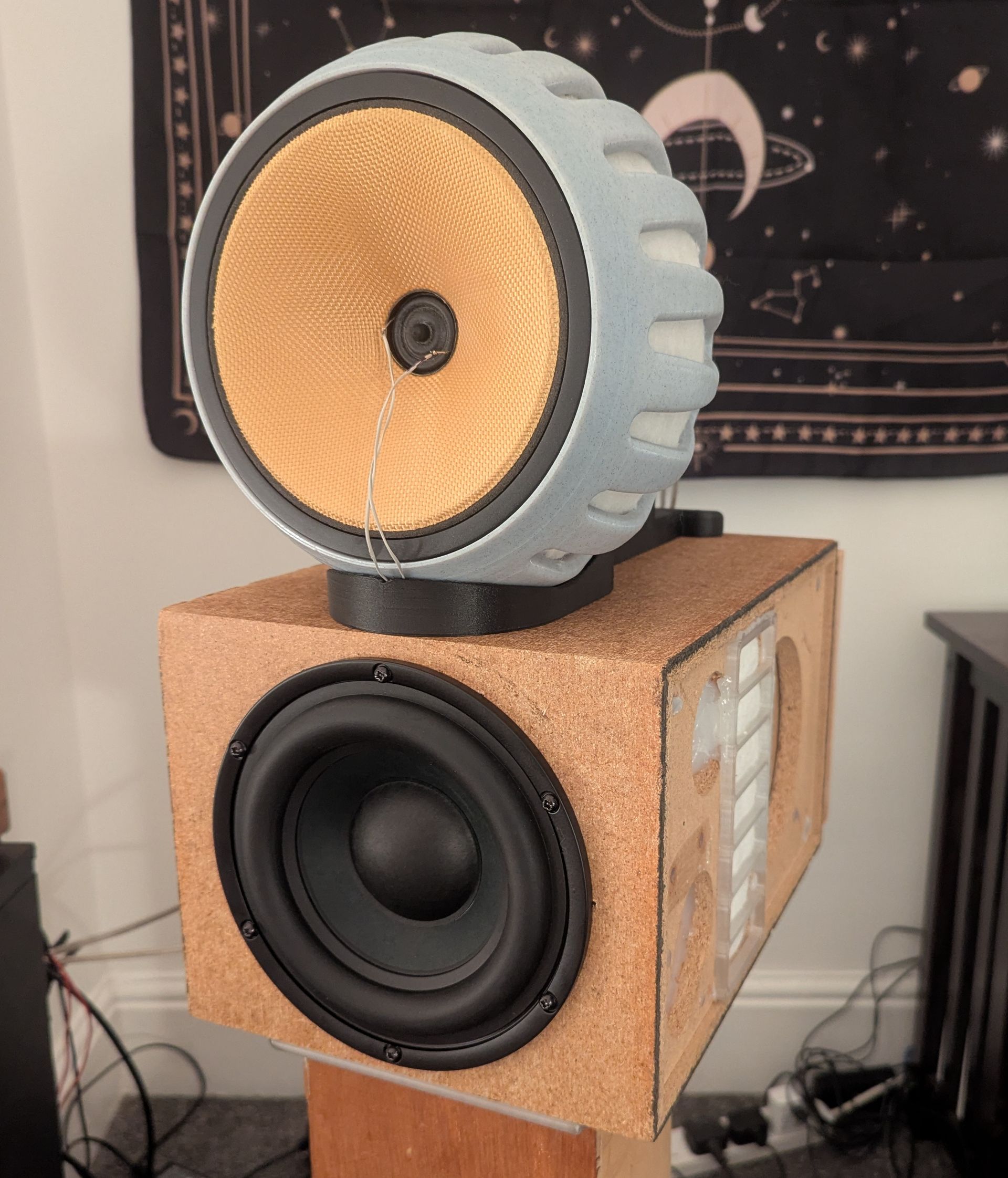
A quick and dirty test. Out with the HDS and in with the BWX. They went from sounding very good to still sounding very good :)
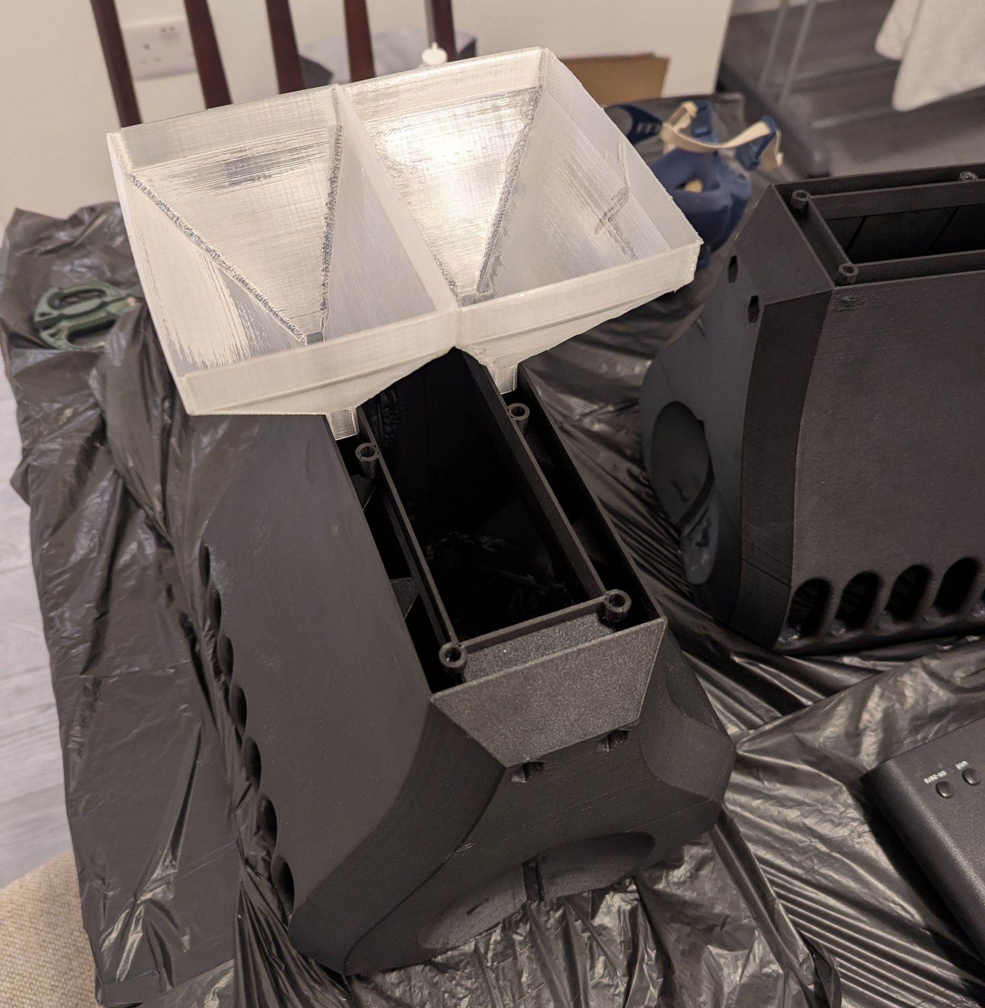
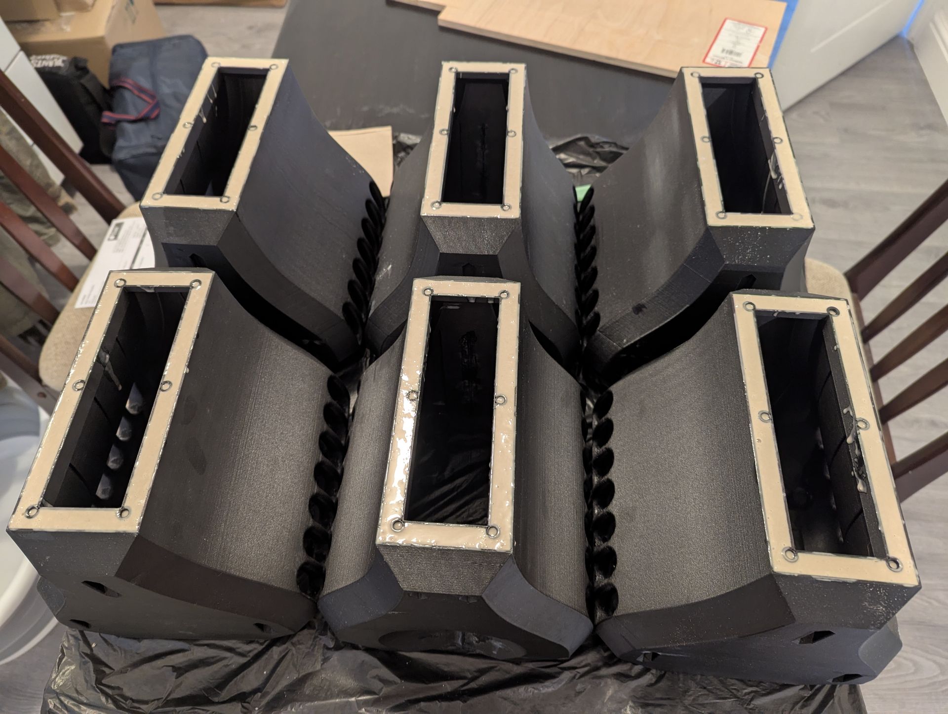
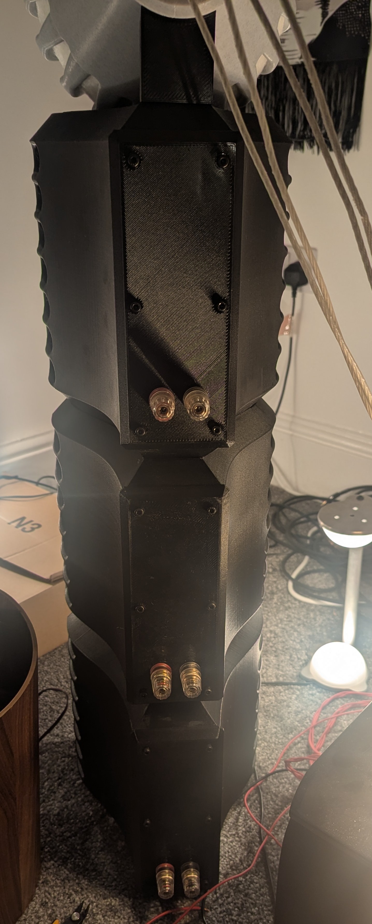
Just like the FST cabinets the bass cabinets were to be 3D printed, as shells, and then filled. As my 3D printer has a limit to the size of the things it can print these were done as one cabinet per driver. This creates an interesting modular approach where it would be possible to use the mid/tops with any number of bass units.
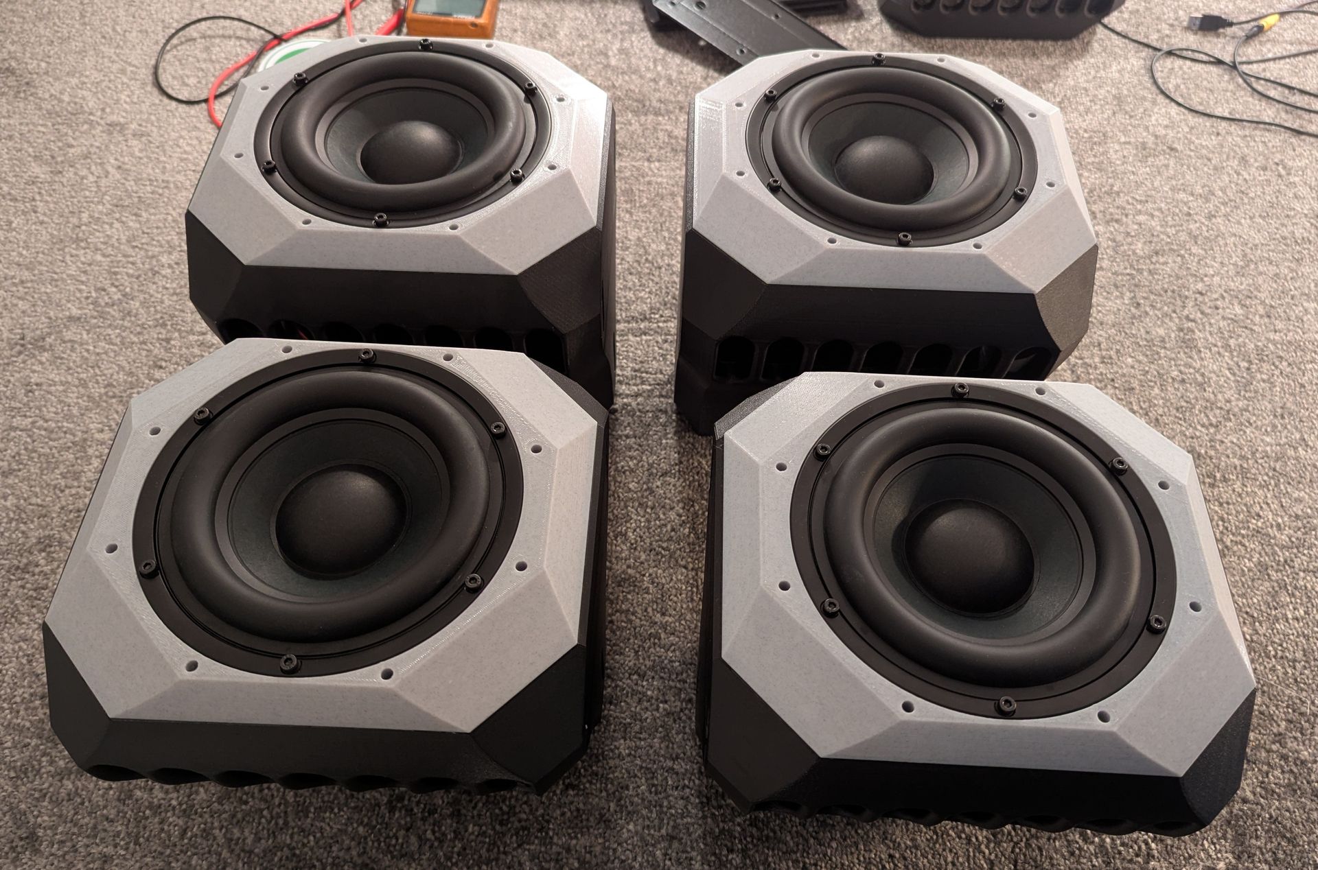
These cabinets were printed out of a carbon fibre loaded PETG filament. Not due to any concerns about strength it just looks good and the texture helps to hide any of the print lines. Below is a 3D printed funnel I came up with to ease the pouring of the marble loaded epoxy into the cabinets.
Just like the FST cabinets the bass cabinets were to be 3D printed, as shells, and then filled. As my 3D printer has a limit to the size of the things it can print these were done as one cabinet per driver. This creates an interesting modular approach where it would be possible to use the mid/tops with any number of bass units.
These cabinets were printed out of a carbon fibre loaded PETG filament. Not due to any concerns about strength it just looks good and the texture helps to hide any of the print lines. Below is a 3D printed funnel I came up with to ease the pouring of the marble loaded epoxy into the cabinets.
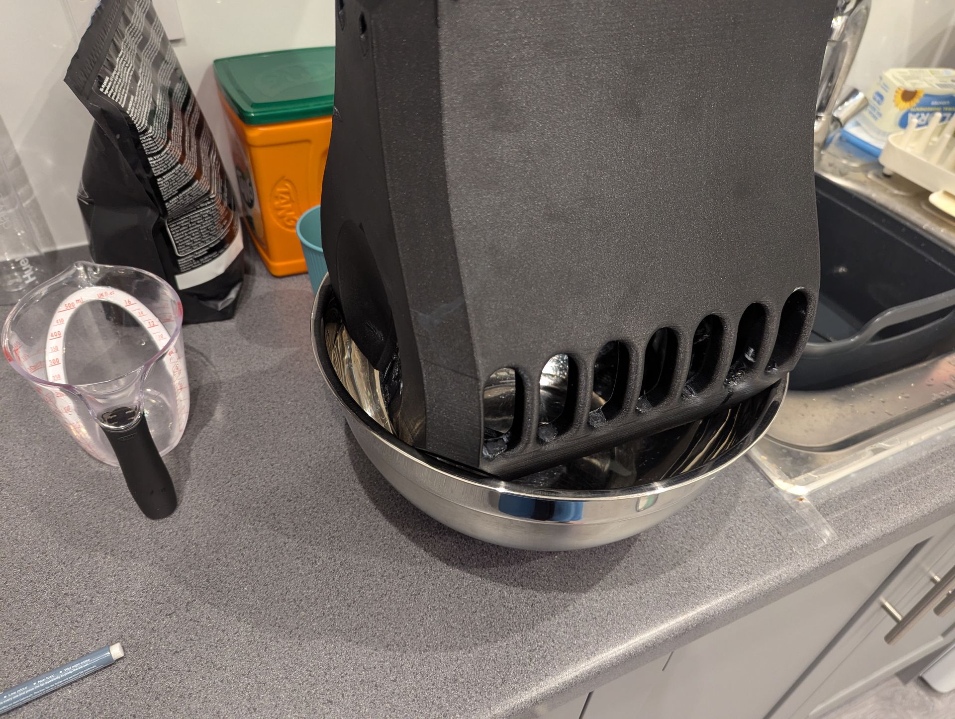
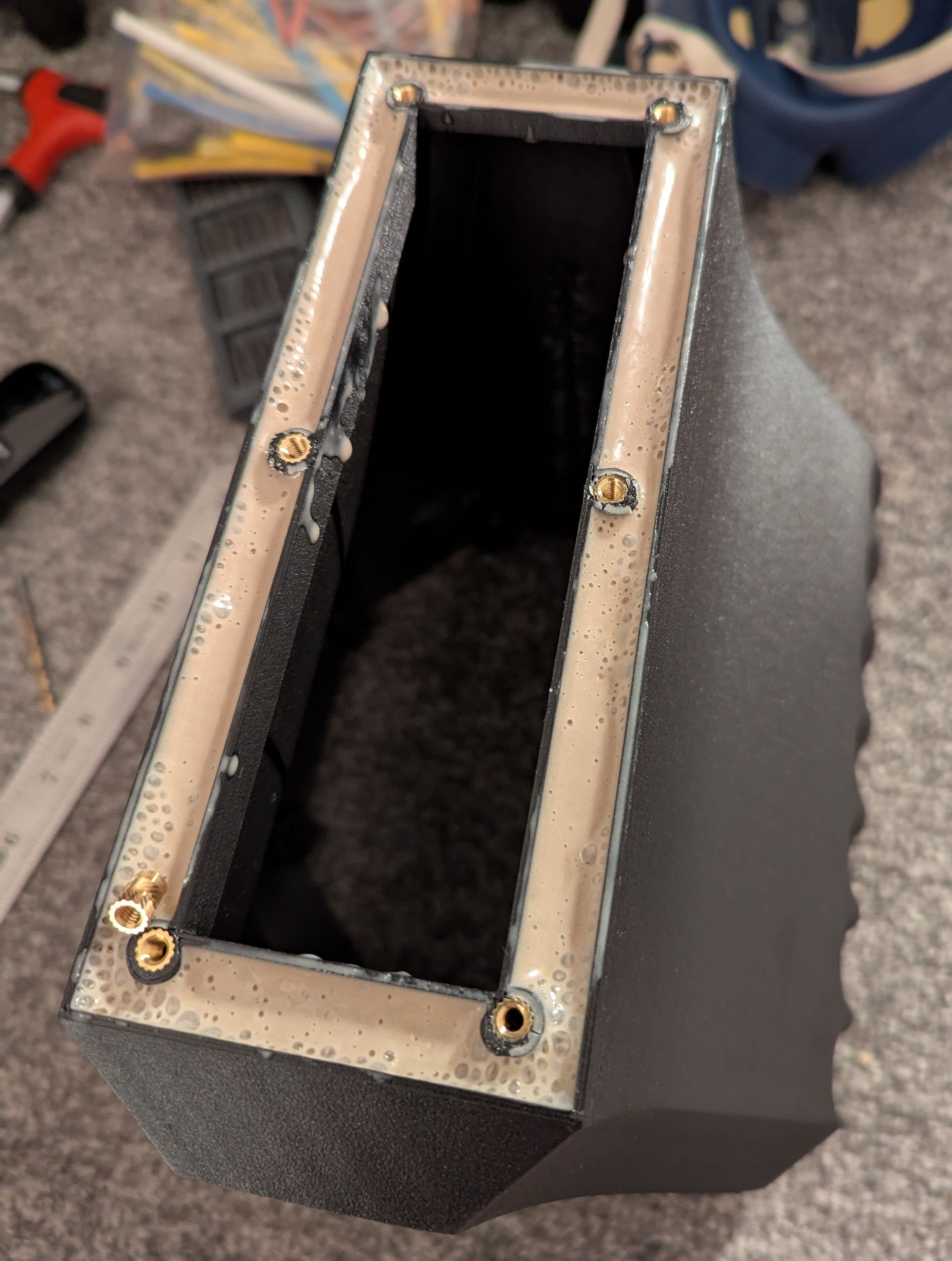
Filling a cabinet with water first of all to check for any leaks. They all leaked and needed sealing in various places with a bit of super glue.
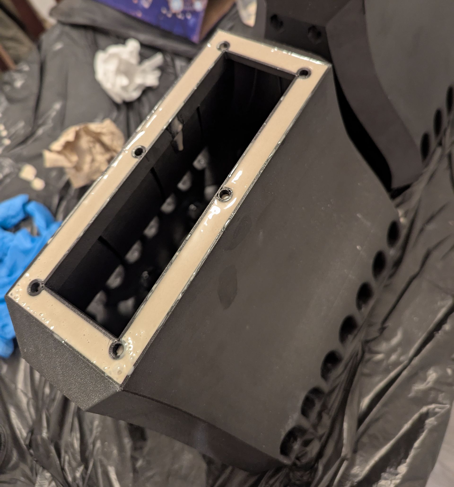
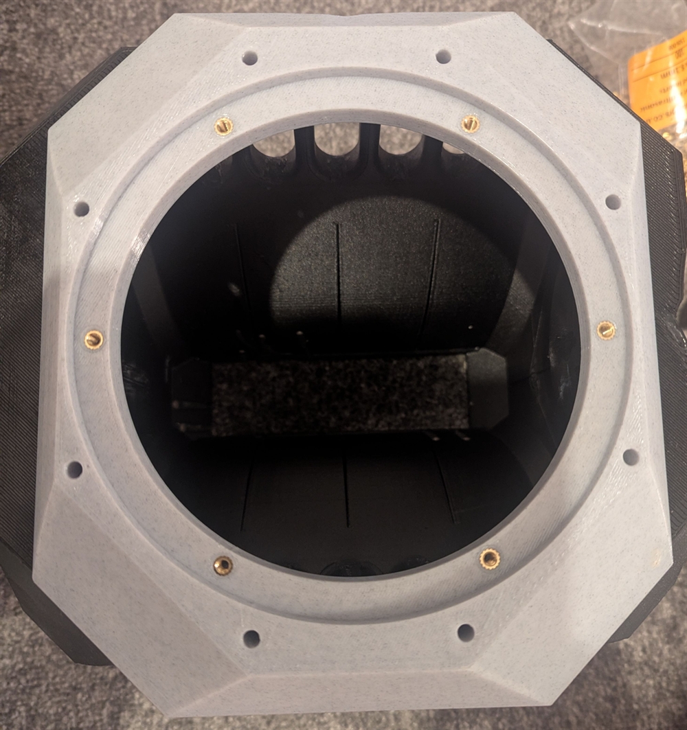
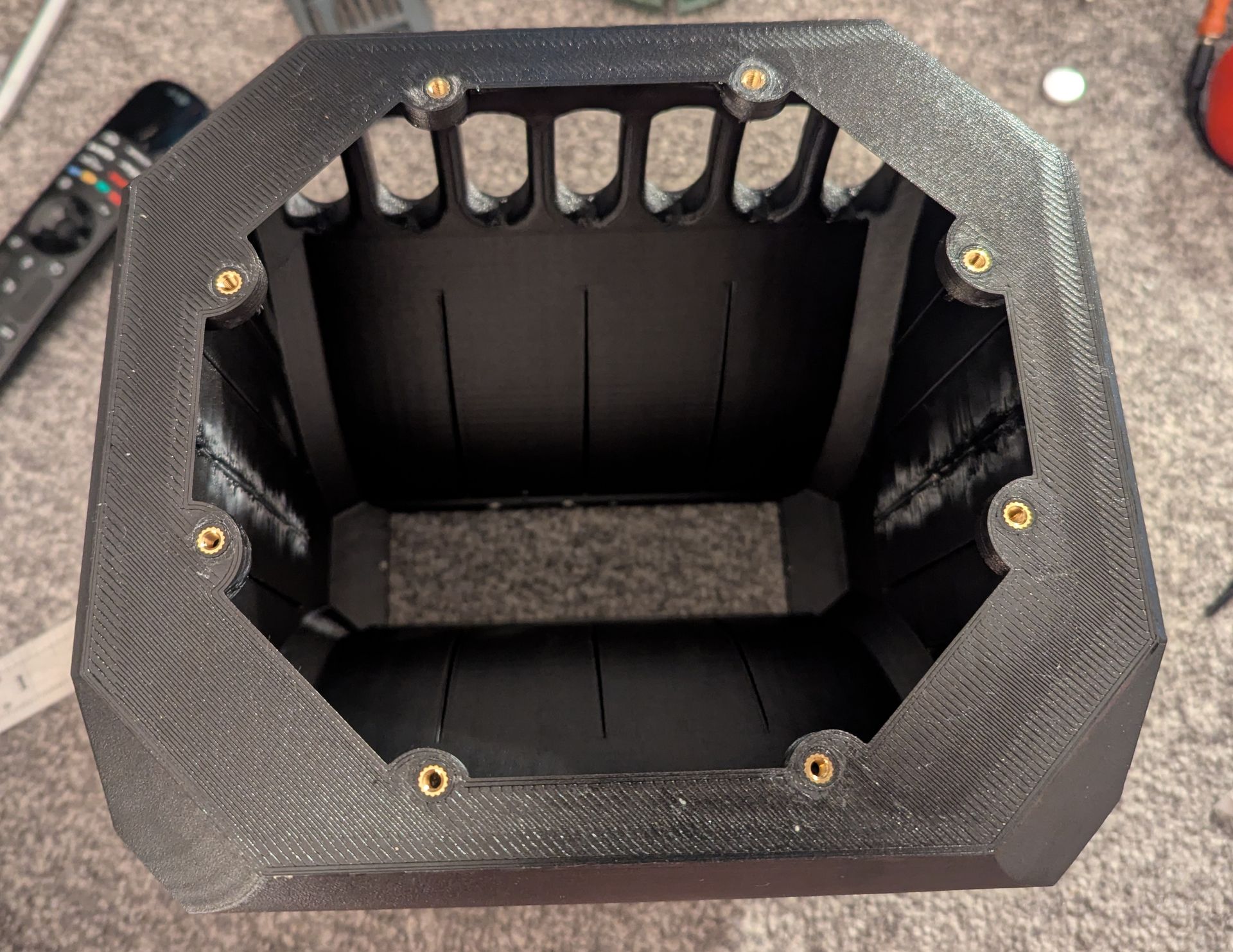
Putting in threaded inserts. As far as I am aware these are designed for ultrasonic insertion into thermoplastics but all DIYers use a soldering iron to press them into a pilot hole.
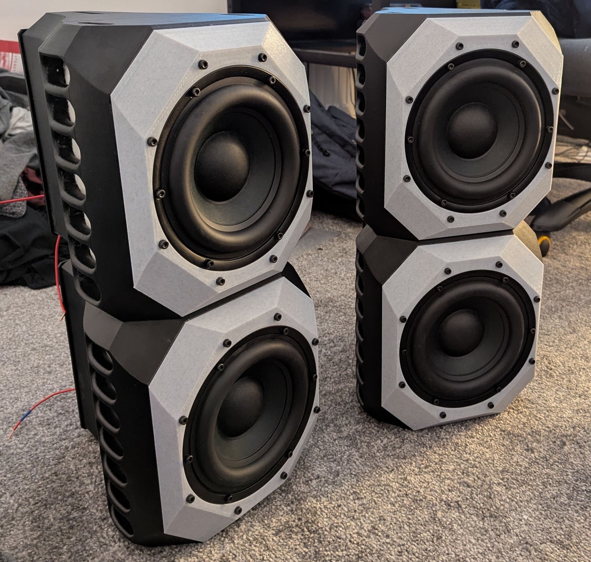
While the individual cabinets weigh quite a lot I didn't take any chances and inlaid a bunch of neodymium magnets into the top and bottom surfaces to help hold them together.
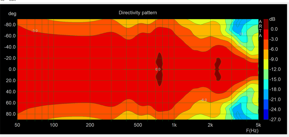
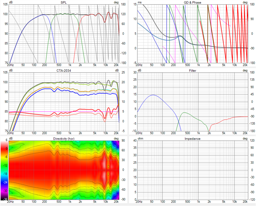
Next up a directivity plot for one of the bass cabinets. As can be seen it has excellent performance but tends towards more of an open baffle at lower frequencies.
And there we have it.
The final bass response was tuned by ear and by using room averaged responses hence the shelved down bass in the plots above. Nevertheless you can see that I have not chosen to EQ them extremely deep because that's what subwoofers are for!
During the development of these I moved house and into a room, with the hifi, that was a lot more reverberant than before. You clap your hands and you can hear the room ring in response however, due to the controlled directivity, this is where cardioids are suppose to shine minimising early reflections and allowing the sound to remain clear and focused. I hadn't even been designing these for the new room but it ended up being an excellent test of how well a cardioid can integrate into reflective environments. If the music abruptly stops you can also hear the decay in the room and you'd expect the stereo presentation to be a mess but it isn't. The cardioid/coaxial keeps it as clear as a bell.