USB DAC
Years ago I built a USB DAC audio interface for my brother. I had intended it for one of my aunts but it refused to work with her laptop, so my brother got it.
This was based around the TI PCM2706, SRC4192 and PCM1794. Time has moved on and while the PCM2706 gave a lot of, easy to implement, functionality it's been significantly left in the dust by more modern designs. Having used the CM6632A in another project I decided to build a replacement unit for him.
To make the replacement worthwhile I wanted to improve upon every aspect of the previous design, both in terms of performance and ease of use. Most notably the previous unit required a separate AC power feed which made it cumbersome to move around. In this replacement unit the entire thing runs directly from the USB cable.
Power mangement and the DAC
As typical USB ports are only specified to provide 500mA, at 5V, this places constraints on the design.
The first issue is the requirement for a split supply for the opamps. Not only would a negative rail be needed but the 5V from the USB rail isn't enough voltage either. This requires a two pronged attack of inverter and boost converter. Luckly the engineers at TI are smart people and have foreseen this kind of situation. They make a handful of chips designed to do just this. Here I chose to use a TPS65131.
One of the traits of the PCM1792A, current output DAC, is that it biases its outputs so that they are always sinking current. This happens regardless of the signal level and when the DAC is outputting all zeros the outputs sink 6.2mA of current. This then swings down to -10.1mA and up to -2.3mA when the output is at full scale. As a result of this, after I/V conversion, the entire voltage swing of the output is offset below ground, within the negative portion of the opamps output range. Of course after the I/V stage comes a differential summing stage. This cancels out the differential negative bias on the I/V outputs and centres the output about ground.
As the I/V stage operates entirely within the negative portion of the opamps output the supply to said opamps needs virtually no positive rail swing at all. Only needing just enough positive potential to ensure that the output swing limits of the opamp are respected so that the signal doesn't clip. The negative rail, on the other hand, needs considerable head room. As the I/V stage requires little in the way of positive rail voltage the requirements for the positive rail fall on the opamps that perform the differential summation. Their output swing is centred around ground so they require a significant amount of voltage swing into the positive direction.
Primarily the output of the DAC is to be used to drive a pair of headphones and, in this case, I chose to use an INA1620, from TI. This opamp sums the differential signal on the output of the I/V stage and drives the headphones at the same time. Whatever lots of people may try and tell you, large voltage swings are not usually necessary for driving high impedance headphones. My brother uses a pair of HD650s and these can reach blisteringly loud volumes without needing insane voltage swings. I too have a pair of 650s and can tell you they go plenty loud enough with only 2VRMS of voltage. To that end I designed the analogue circuitry, after the DAC, to achieve a voltage swing just in excess of 2VRMS.
Looking at the INA1620s datasheet it says that with a 600ohm load it can swing to within 1V of the rail voltage. With lower impedances this would be even lower, but given a 2VRMS signal only needs to swing to a peak of ~2.8V, powering the opamp from a 5V positive rail should provide more than enough headroom for a full scale output from the DAC.
Ironically what ended up setting the maximum requirement for the positive supply rail wasn't the opamps at all, rather it was the drop-out of the 5V LDO, necessary, for the DACs analogue circuitry. While LDOs may be able to operate with only a small drop between their input and output their performance usually improves when provided with at least 1-2V of headroom. Here the LDO used was the ADP7118, from Analog Devices, and I chose to set the positve output from the boost converter to 6.5V.
With the component values selected for the I/V stage and the NE5534 opamps used, setting the output of the inverter to -12V worked very well. Post switching converter regulation being provided by a TPS7A39 dual, split supply, LDO.
The main advantage of using asymmetric power supplies, for the analogue circuitry, being that it dramatically reduces the power consumption. Usually this isn't important for most hifi applications, but here, it was necessary.
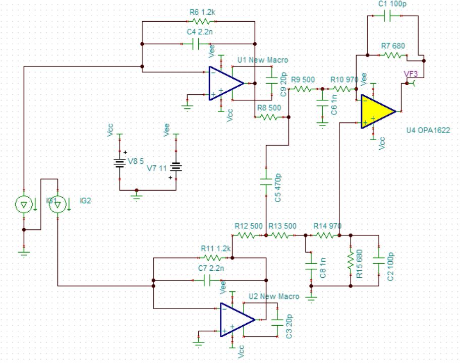
Above is a circuit diagram showing the analogue output stage. The final component values were slightly different from those above but the basic idea is the same. I chose to use a passive low pass filter after the I/V stage to reduce the capacitive loading on the INA1620 (modelled here as an OPA1622). An active filter places a cap in the feedback path of the opamp and this can increase distortion with some opamps, I didn't want to bother with that. As the resistor values, acting as the source impedance for the INA1620, were low enough in value they weren't going to adversely affect the noise/distortion performance of the system by any significant amount. TINA TIs predicted SnR being greater than 126dB without any kind of weighting.
Indeed the analogue performance of the DAC is pretty impressive managing to reach and exceed the datasheet performance for the PCM1792A
Indeed the analogue performance of the DAC is pretty impressive managing to reach and exceed the datasheet performance for the PCM1792A
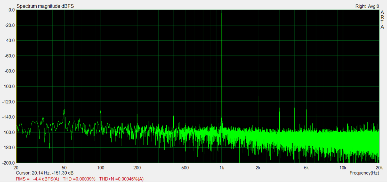
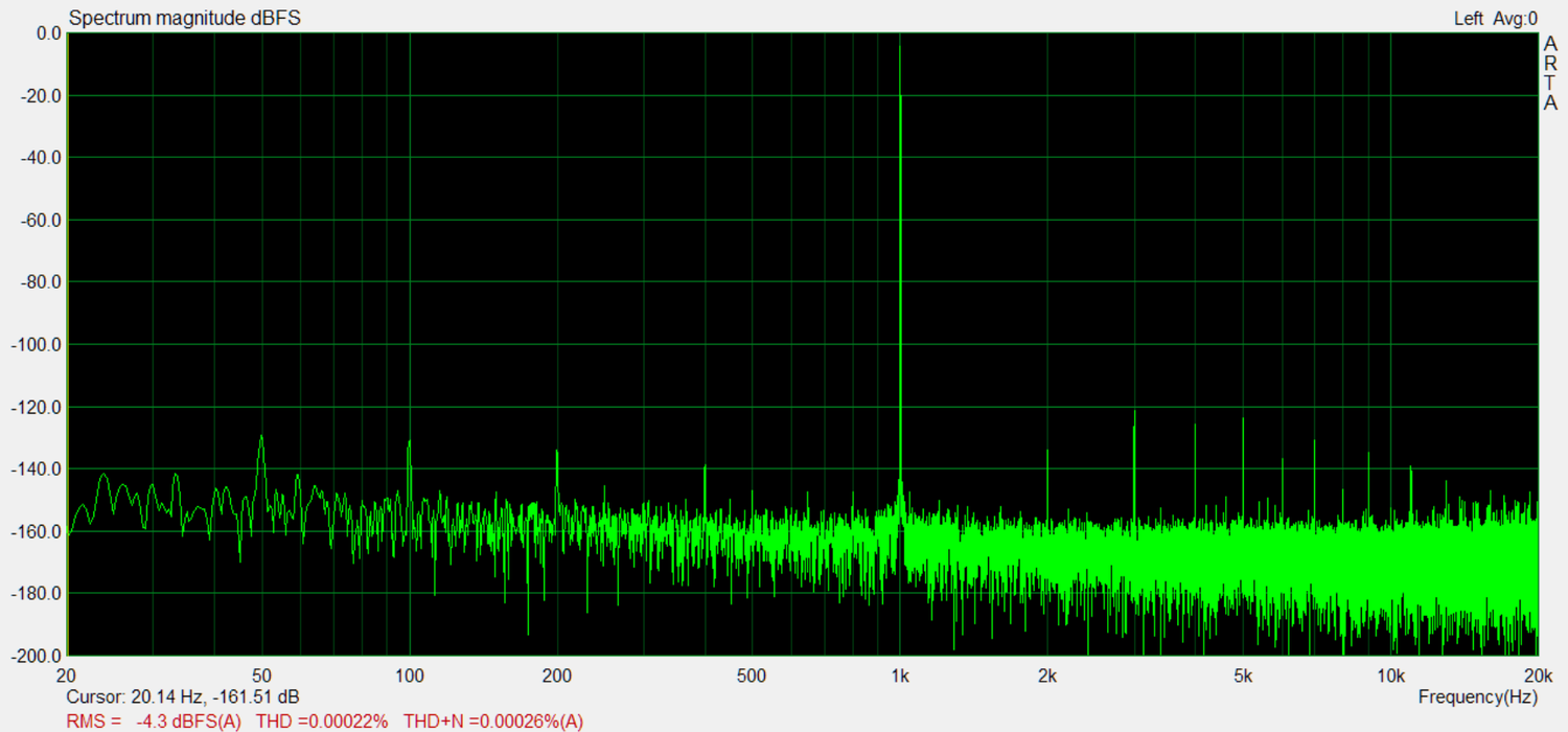
Both the above graphs were with the DAC operating at 96kHz with 24bit data. One graph per channel.
In another article I wrote how I had struggled to get the PCM1792A to perform correctly. I would always get excessive distortion and I could not explain why. I started out using the THS4031, high speed, opamp in the I/V stage. Once again I was seeing high levels of distortion, but the THS isn't happy with a capacitor in the feedback network and to isolate it you typically place a small resistor in series with said capacitor say 20-100ohm.
Not happy with the high distortion I decided to remove the isolation resistor and this improved things in one respect but made them worse in another. Seeing that this was a two steps forward, one step back situation I replaced the opamps with the NE5534 and the distortion ended up as pictured above. I am absolutely sure that I tried this years ago but without success. The only difference being that then I was using small 0805 film caps. This time round I decided to use C0G caps as they aren't easily damaged by the heat from a soldering iron.
It would seem that the PCM1792/4 output some high frequency noise that really needs handling properly in the I/V stage for things to work correctly. Indeed I had better success with the chips mounted on SMD to through hole adaptors. This, potentially, makes some sense as the suboptimal routing of the traces, in such a situation, would increase the parasitic capacitance of the traces whilst also adding in more inductance and therefore filtering out some of the noise that would otherwise trouble the opamp. Either way I am glad that I managed to get the PCM1792A working properly here.
For the volume control I simply used the PCM1792s onboard, digital, volume control. The input for this being a simple potentiometer feeding the microcontrollers ADC with a DC voltage.
The ADC and mic input
As my brother games quite often, and when doing so uses a microphone, I figured it would make sense to include an ADC and microphone preamp. I already had the PCM1861 sitting on a shelf so decided to use it. This chip conveniently comes with an analogue front end that you can configure for various amounts of fixed gain. This is aimed directly at having small electret mics interface directly with the ADC without requiring any additional circuitry. Indeed the ADC can output the voltage required to bias such microphones too, and while these features are useful, what I really wanted to be able to include was variable mic gain. TI solve this issue with the SPI/I2C configurable PCM1863 as this has variable gain within the AFE but the pin configurable PCM1861 does not. With the PCM1861 you can choose between 2 different gain values.
To solve this issue I built a simple mic preamp around a NJM4580 I had lying around. One opamp buffering the microphone input and the second one providing the variable gain of 20x. Coupled with the 12dB gain setting on the PCM1861 this provided a useful range that would suit most situations.
The CM6632A
With the SDK you can find online you'd figure that implementing the CM6632A would be quite straightforward. For the most part it is but it does have one rather large issue. When I first started to experiment with the CM6632A I had it connected up to an AK4499 DAC and, while distortion was low, I was seeing noise levels far in excess of what I was expecting. At first I figured this was due to the implementation of the AK4499 but after scratching my head with that I figured I should try another digital source. Out with the CM6632A and in with the WM8804. This solved the noise floor issue. While the WM8804 had greater periodic jitter it had much lower random jitter with the noise floor dropping by more than 10dB. The question then became what would happen if the master clock, feeding the DAC came directly from the oscillator feeding the CM6632A instead of the buffered master clock output of the CM6632A itself. Boom, problem solved. So, for whatever reason, the CM6632A is adding in a lot of random jitter.
As the CM6632A operates synchronously, to the oscillators feeding it, theoretically all you'd need to include is some external clock buffering, and switching. That way you can feed the DAC directly from the oscillators, rather than from the CM6632A and to provide a way of changing clock frequency based on the sample rate. This works very well except you have to deactivate MCU_FEEDBACK in the asynchornous transfer control options otherwise the clocks end up out of sync. For some reason MCU_FEEDBACK causes the clocks on the output of the CM6632A to over/under run by a sample every now and a again and you hear a pop/click through the speakers.
In this system I went with some tri-state logic gates for buffering the two oscillators and to also enable switchinig of the clocks feeding the DAC. I then used an MCU to interface with the CM6632A, altering the CM6632As firmware to output a signal over I2C to let the MCU know what sample rate was in use. The MCU then swapping between the correct clock source for the DAC.
The PCM1792As noise floor wasn't impacted quite as significantly as the AK4499s was but you definitely wanted the improvement. I did try all sorts of firmware alterations with the CM6632A but nothing would get rid of that random jitter problem. It makes me wonder if the external memory, with all of its associated traces and high speed switching, contributes to this. Perhaps running the MCU on board the CM6632A with a spread spectrum external oscillator would help.
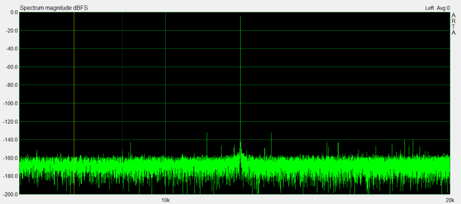
Having talked about random jitter here is a picture of the periodic jitter of the system. This is for 48k, the results for 44.1k were even better but I accidentally lost that graph. Needless to say I used the two least expensive clocks I could find and neither of them had jitter levels approaching what would be considered audible. I mainly bought these clocks just for proof of concept. I fully intended on swapping them out for NDK NZ2520SDA oscillators, but after seeing how well they performed I didn't really see any point. Note that the NDK oscillators still have the same trouble with random jitter in the CM6632A. This isn't because of the clocks used.
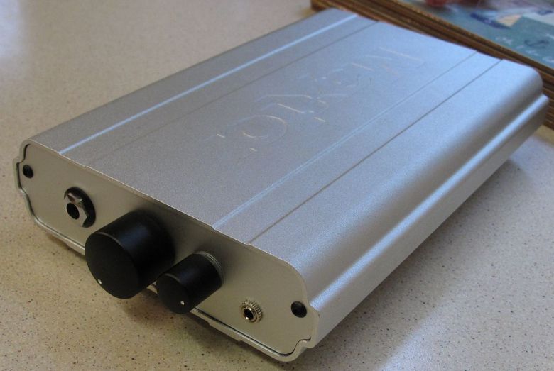
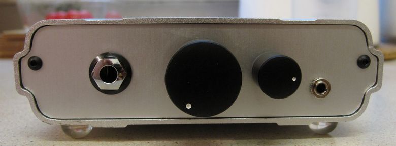
The case for this came from an old external hard disk. I fabricated new front and back plates from anodised aluminium but very little else, besides a few holes, were required to make this work. I rather like the end result.
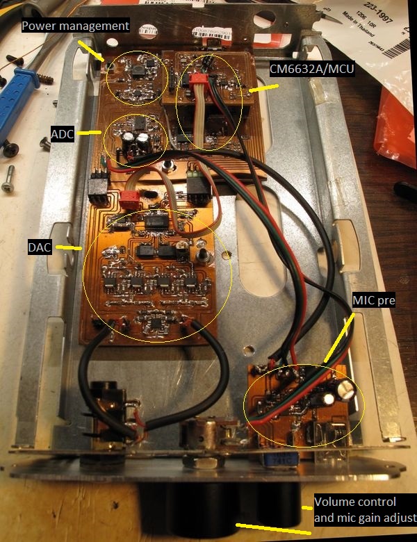
The above image shows the various sections of the design. You'll notice that you can't really see the CM6632A. This is because it's sitting below the MCU/clock distribution board.
As you can see the unit performs very well and certainly puts to rest the concept that you cannot get good measured performance from devices powered solely from USB power. It also sounds excellent.