Waves
Sometimes in life you just want things to be simple and loudspeaker building is no exception. This is even more so when one lives with chronic health conditions and hence this design was born.
Both the W15CYs and the XT19s had been sitting on a shelf and I had always wanted to do a waveguide design with the W15. It is an excellent driver and having experimented with it in combination with waveguides before I felt it deserved a design of its own.
The XT19 I had been less impressed with but this was mainly because of its off axis performance (high dispersion) not mixing well with my room and creating a sound I didn't find acceptable. The obvious answer to this was to shape and control its dispersion with a waveguide and with the overall diameter of the W15 the WG 148 R made perfect sense.
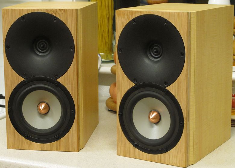
For those of you with good eyes you may have noticed, in the picture above, that the loudspeakers use a pre fabricated cabinet. In fact these are based on a second hand pair of Tannoy's MX1 loudspeakers. I managed to purchased these from ebay for £50, and given their vintage, they were in excellent condition. The majority of the cabinet is made of particle board with the front baffle adding in a layer of MDF for increased ridigity and improved machinability for the driver cutouts. The finish is a rather nice looking vinyl wrap and like the particle board was most likely chosen to keep costs down. Vinyl faux woods are often frowned upon but in this case and unless up close you'd be hard pressed to distinguish it from a lightly grained, satin, real wood finish. The price was certainly right, especially as it came with the original drivers, crossovers and binding posts, the only thing I needed to do was glue on a new front baffle and I was ready to go!
For the front baffle I chose to go with layered bamboo lumber, or LBL, this has gained a decent amount of traction in some DIY circles and for good reason, it posses good internal damping and is very rigid. These were in fact recycled chopping boards that were bought specifically for the loudspeakers and cost around £5 each. LBL machines very smoothly and produces a very attractive and resilient surface even when completely unfinished. As can be seen the front baffle dimensions are very well suited to the drivers used and extensive reseach was done on small second pairs of loudspeakers as to what would be the most suitable.
Both the W15CYs and the XT19s had been sitting on a shelf and I had always wanted to do a waveguide design with the W15. It is an excellent driver and having experimented with it in combination with waveguides before I felt it deserved a design of its own.
The XT19 I had been less impressed with but this was mainly because of its off axis performance (high dispersion) not mixing well with my room and creating a sound I didn't find acceptable. The obvious answer to this was to shape and control its dispersion with a waveguide and with the overall diameter of the W15 the WG 148 R made perfect sense.
For those of you with good eyes you may have noticed, in the picture above, that the loudspeakers use a pre fabricated cabinet. In fact these are based on a second hand pair of Tannoy's MX1 loudspeakers. I managed to purchased these from ebay for £50, and given their vintage, they were in excellent condition. The majority of the cabinet is made of particle board with the front baffle adding in a layer of MDF for increased ridigity and improved machinability for the driver cutouts. The finish is a rather nice looking vinyl wrap and like the particle board was most likely chosen to keep costs down. Vinyl faux woods are often frowned upon but in this case and unless up close you'd be hard pressed to distinguish it from a lightly grained, satin, real wood finish. The price was certainly right, especially as it came with the original drivers, crossovers and binding posts, the only thing I needed to do was glue on a new front baffle and I was ready to go!
For the front baffle I chose to go with layered bamboo lumber, or LBL, this has gained a decent amount of traction in some DIY circles and for good reason, it posses good internal damping and is very rigid. These were in fact recycled chopping boards that were bought specifically for the loudspeakers and cost around £5 each. LBL machines very smoothly and produces a very attractive and resilient surface even when completely unfinished. As can be seen the front baffle dimensions are very well suited to the drivers used and extensive reseach was done on small second pairs of loudspeakers as to what would be the most suitable.
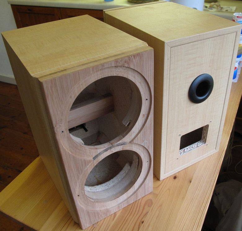
As nice as the original cabinet is, it didn't contain any internal bracing and wanting to keep the internal cabinet volume as high as possible I chose to simply add in a cross brace made of some space LBL.
The most obvious first issue regarding this design was the waveguide, just how would the XT19 interface with it and what would be the best way to fix it into place? As luck would have it everything came together extremely well.
The most obvious first issue regarding this design was the waveguide, just how would the XT19 interface with it and what would be the best way to fix it into place? As luck would have it everything came together extremely well.
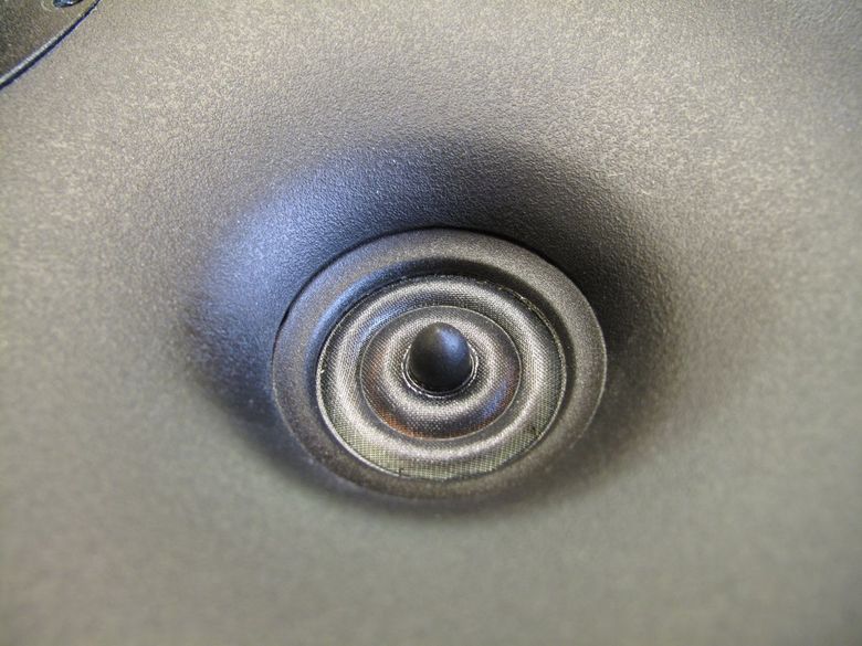
The first thing of concern is how well the waveguides throat matches up with the tweeters faceplate. As can be seen the match up here is pretty much flawless and requires no additional attention.
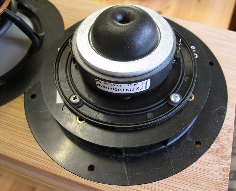
Next is how is the tweeter going to attach to the waveguide? As can be seen the waweguide itself comes with threaded inserts for use with Visaton tweeters but obviously these aren't suitable for the XT19. Luckily all you need to do is drill some new holes into the waveguide and use bolts to fix the tweeter into place.
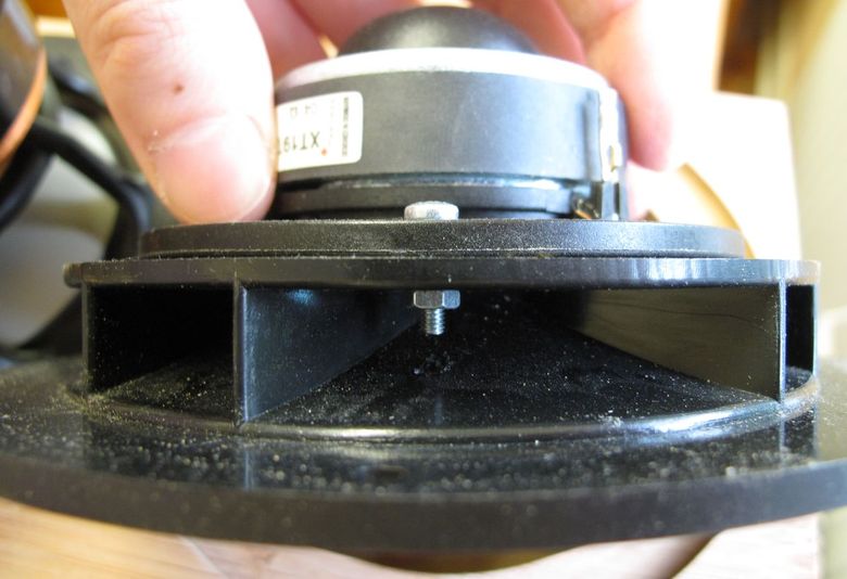
As can be seen it is easy to modify the waveguide for whatever tweeter you wish to attach. Now the XT19s faceplate is ever so slightly non flat. This causes the plastic faceplate to warp, or deform, around the screw holes. This was a cause of concern as it was possible that this could cause the dome/coil assembly to deform and cause coil rubbing and therefore distortion. Luckily this didn't happen, making the XT19 extremely easy to mate with the WG 148 R. Next up is to measure the performance of the combination.
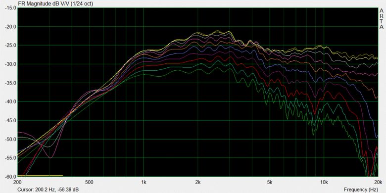
Above can be seen how the XT19 measures when on the WG 148 R. As you can see the top octave issues, usually associated with dome tweeters and waveguides, aren't present. This is highly typical of ringradiator tweeters and is indeed quite welcomed. This looks quite nice, but to see exactly what's going on I prefer to use a contour plot directivity map.
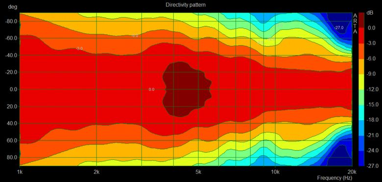
Ah, much better! As you'd expect the directivity begins to narrow towards the lower end of the tweeters response but unusually it widens again above 3kHz. With a waveguide of this size, what we'd be hoping is for the response to be controlled so that you'd be around 6dB down, at 45 degrees, at around 3kHz. This would make it perfect for a directivity match with 5" soft coned driver when crossed at around 3kHz but due to the directivity widening at this point it does reduces it's useability somewhat. Still some waveguide is better than no waveguide, but in this case you'd be bettter off crossing over low, before the waveguide starts to control directivity and before the woofer starts to beam.
This works out well because I was never going to cross the W15 over at 3kHz to start with and as is typical with metal coned drivers the W15 has a substancial peak in its third order distortion at 1/3 the frequency that the cone rings at. In this case that is 2.7kHz necessitating a low crossover point. Now the XT19 isn't particularly capable when it comes to low crossover points but the waveguide loading goes a very long way into helping with this.
Measuring for crossover design we end up with this.
Nothing unusual here with a large hump seen towards the tweeters low end. This behaviour being what is responsible for easing the tweeters load down low.
Again the W15 measures in a way that we would expect. Note the falling response, due to baffle step losses, and the massive peak at 8.2kHz indicative of stiff cones. It has been said that the W15CY001's breakup has varied from its initial introduction, starting out a little lower in frequency, and then rising up to the 8.2kHz frequency that we see today. My W15s are about 15years old and measure like the drivers we see today. Good news for those wanting to build this design.
The crossover took a bit of effort to come into place but it wanted to naturally fall on a 4th order acoustic at 1.8kHz. I was a little concerned with this because I wanted to crossover more around 2,2kHz, just to give the XT19 an easier time, but everything simply worked better with it down a little lower. Of course there are good reasons for crossing lower, a better vertical off axis performance and greater suppression of the W15s third order distortion peak but measuring would be needed to see if the low xover point would be acceptable.
As can be seen the drivers integrate very well and around 4dB of bafflestep compensation was chosen.
The woofers xover is nice and simple but gets the job done admirably.
The woofers xover is nice and simple but gets the job done admirably.
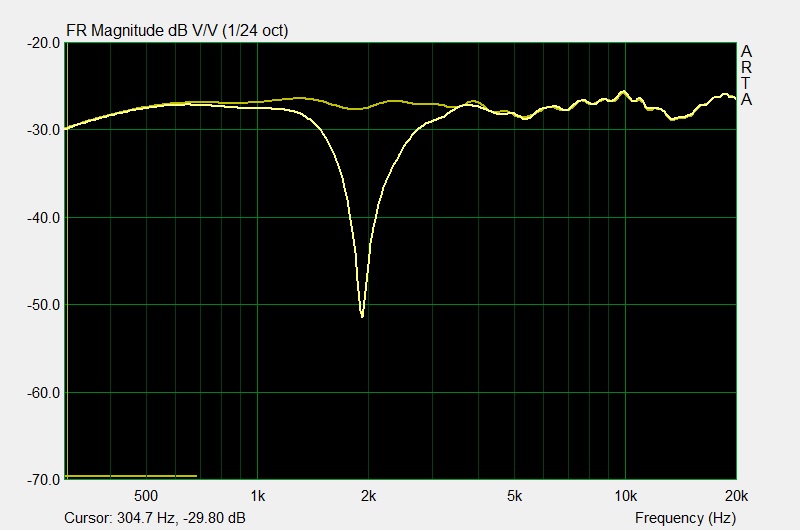
It is essentially a 2nd order electrical filter with a capcitor placed across the primary inductor to form a notch filter. I purchased my xover components from intertechnik.de and the primary inductor was chosen with regards to price and towards keeping the DC resistance of the inductor low. Here the value is 0.69 ohms. Those of you in the US have access to madisounds sledgehammer coils and can more easily keep the DCR low, I wish we did in the UK!
Above is the woofers transfer function showing the notch fitler.
The tweeters xover is, alas, not as simple, but at least you can use small, inexpensive, aircored inductors for the notch filters. As can be seen R1071 and R1081 have a considerable resistance and need to take into account the DC resistance of the inductors. R1071 = 1.86 ohms. If your inductor, L1071, has a DCR of 1 ohm then you need to use a resistor of around 0.86 ohms.
Above is the tweeters transfer function where you can see the effect of the notches.
As is usual care was taken to make the speaker easy enough to drive.
With regards to the box alignment you can see here that the port is tuned to a rather high 55Hz. This unstuiable for the W15 which means that the Tannoy fitted port needs replacing.
With regards to the box alignment you can see here that the port is tuned to a rather high 55Hz. This unstuiable for the W15 which means that the Tannoy fitted port needs replacing.
Above is the intended bass response for this design. Working into the 6-6.5 litre volume cabinet with a port tuning of 40Hz. This is a low tuning for such a small cabinet and requires a port of relatively small diameter in order to fit in. I had to use the streamline30 from intertechnik.de to acheive this and without any modification to its length either. This port has a rather small diameter and this is a design that would actually benefit from a passive radiator being placed on the back of the cabinet. Wind speed noise can be heard at higher drive levels, but in acual listening it hasn't proved to be a problem.
For the crossovers I went with a mixture of non polar electrolytic and polypropylene capacitors and a mixture of air and ferrite cored inductors.
For the crossovers I went with a mixture of non polar electrolytic and polypropylene capacitors and a mixture of air and ferrite cored inductors.
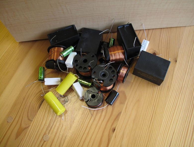
A pile of components.
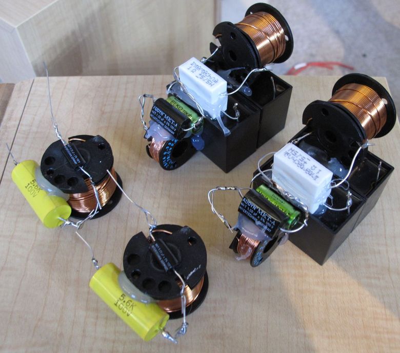
The crossovers assembled!
Of course the acid test is always seeing how your finished loudspeaker measure. Simulation is one thing but the real world is another. The most important thing is seeing if the reverse null is good as this confirms whether or not your drivers are well integrated and whether or not your original phase data was accurate.
Of course the acid test is always seeing how your finished loudspeaker measure. Simulation is one thing but the real world is another. The most important thing is seeing if the reverse null is good as this confirms whether or not your drivers are well integrated and whether or not your original phase data was accurate.
Luckily we can say here that it was. That notch is exactly what we want to see! The main disparity between the simulation is the peak at 10kHz. This happens when component tolerances come into play, narrow notches can be quite sensitive to component values. Thankfully the issue is minor.
Next up is the final off axis response. If you remember I mentioned the slight widening of the dispersion of the waveguide at around 3kHz and this is far easier to see in the finishes loudspeaker.
Next up is the final off axis response. If you remember I mentioned the slight widening of the dispersion of the waveguide at around 3kHz and this is far easier to see in the finishes loudspeaker.
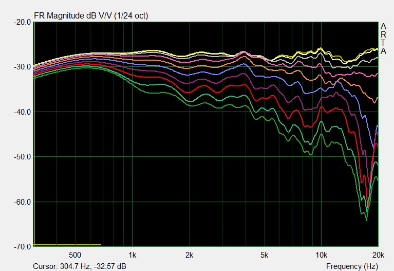
First of all we can see the nice smooth off axis response that we'd expect from a waveguide design. As you can see though at around 3kHz there is a rise in output, thankfully this isn't anywhere half as bad as I originally thought. The measurements are from zero degrees out to 90 in ten degree steps.
Another concern was the low crossover point and the XT19 so lets take a look at that.
Another concern was the low crossover point and the XT19 so lets take a look at that.
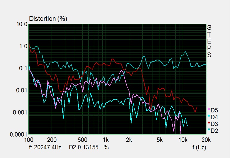
The above measurement is done at 2.83V. Now this isn't a sensitive loudspeaker. We're talking about an 86dB driver, 4dB of bafflestep compensation and some insertion losses from the primary inductor. These end up at around 81.5dB. Still this is quite loud and the distortion is exemplary. But what about with things a little louder?
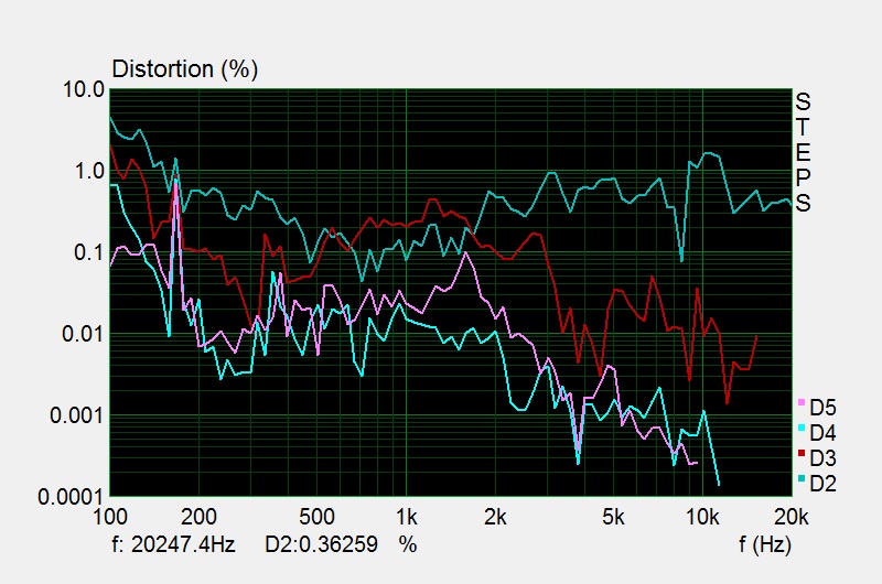
Here we're at +10dB, so around 91.5dB and the distortion profile has barely changed. Ring radiators are known for their highish levels of 2nd order distortion so this is of no surprise but what's rather funny is that although we were worrying about the tweeter it is in fact where the loudspeakers linearity is at its best with all higher order harmonics falling when the tweeter takes over.
These are obviously a very low distortion loudspeaker and we can see that the 2.7kHz peak in third order distortion has been well controlled. Yes it's still there, it's still dominant (remember the tweeter takes over at 1.8kHz) but this highlights why you need to really cross low with metal coned drivers.
So how do these sound? In a word excellent but otherwise polite would be the word I'd use to describe them. As is usual with waveguide designs the speakers make a good job of disappearing, drawing very little attention to themselves and creating a wide spread of sound. These are not speakers that jump out at you in any way, they are very detailed but instead of pushing detail down your throat these simply offer it to you. Another nice thing is that these do not trouble my hyperacusis in any way, which is always the sign of a good design!
If you wish to build these yourself you can either copy what I did and buy a second hand pair of Tannoy MX1s and recycle the cabinets or build your own. Due to the waveguide baffle edge diffraction is less of a concern than with other designs but some care must be taken to ensure that certain parameters are kept the same. The first is the width of the loudspeakers, these are 165mm wide, and the width is directly responsibly for how bafflestep operates and must be adhered to. The second is the driver separation. The distance between the centre of the tweeter and woofer is 133mm.
Apart from the above you are largely free to do as you please with the rest of the cabinet. This means that you can change the height and depth to suit your envionment. Of course the cabinet volume is important and for this design you should really stick to 6-7 litres with a similar frequency of port tuning. If you wish you can build these sealed to mate with a subwoofer but if you do I wouldn't go any smaller than 3.5 litres with the cabinet heavily stuffed. The other option would be to build them as a floor stander to really get as much bass out of the W15 as you can. In this case I wouldn't go any bigger than 15 litres and tune them to 35Hz with light stuffing. If you do build a floor stander you will need to suppress any pipe resonances created with the long narrow cabinet. To do this ensure heavy stuffing somewhere along the enclosure but well away from the port. A 15 litre cabinet tuned to 35Hz creates an extended bass shelf alignment whcih might sound a little lean. A more optimum scenario would be to reduce the volume to 10 litres and tune to 40Hz.